
User's Manual
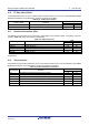
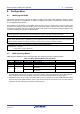
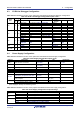
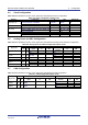
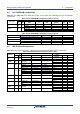
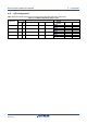
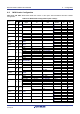
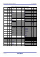
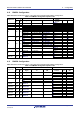
Table Of Contents
- 1. Overview
- 2. Power Supply
- 3. Board Layout
- 4. Connectivity
- 5. User Circuitry
- 6. Configuration
- 6.1 Modifying the RSSK
- 6.2 MCU Operating Modes
- 6.3 E1/E2 Lite Debugger Configuration
- 6.4 Power Supply Configuration
- 6.5 Clock Configuration
- 6.6 Analog Power and ADC Configuration
- 6.7 CAN Configuration
- 6.8 I2C & EEPROM Configuration
- 6.9 IRQ & Switch Configuration
- 6.10 LED Configuration
- 6.11 MCU Header Configuration
- 6.12 PMOD1 Configuration
- 6.13 PMOD2 Configuration
- 6.14 Bluetooth® Low Energy (BLE)
- 6.15 Serial Sound Interface (SSI)
- 6.16 Touch Interface Configuration
- 6.17 USB to Serial Configuration
- 6.18 USB Configuration
- 7. Code Development
- 8. Additional Information
- 9. Certification of Compliance
Renesas Solution Starter Kit for RX23W 6. Configuration
R20UT4446EG0102 Rev. 1.02 Page 26 of 41
Jun 22, 20
6.8 I2C & EEPROM Configuration
Table 6-8 and Table 6-9 below detail the function of the option links associated with I2C & EEPROM
Configuration.
Table 6-8: I2C & EEPROM Configuration Option Links (1)
Signal name
MCU
MCU Peripheral Selection
Destination Selection
Pin
Port
Signal Fit DNF
Interface
/Function
Fit DNF
P17 B1 P17
E2P-SDA
R61
R72
U3.5
-
-
SSITXD0
R72
R61
P17
-
-
E2P-SCL C3 P16
E2P-SCL
R200
R201
U3.6
-
-
USB0-VBUS
R201
R200
J4.2
R202
-
P16
-
-
P16
-
-
Table 6-9: I2C & EEPROM Configuration Option Links (2)
Reference
Configuration
Fit
DNF
Related Links
SDA0, SCL0
Connect pull-up resistors to Board_VCC.
R29
R28
U3
Connect pull-up resistors to Board_5V.
R28
R29
U3
WP
EEPROM Write protect.
R39
-
U3
A0, A1, A2
Device address (0xA6).
R50, R52, R55
R51, R53, R54
U3
Device address (0xA4).
R50, R53, R55
R51, R52, R54
U3
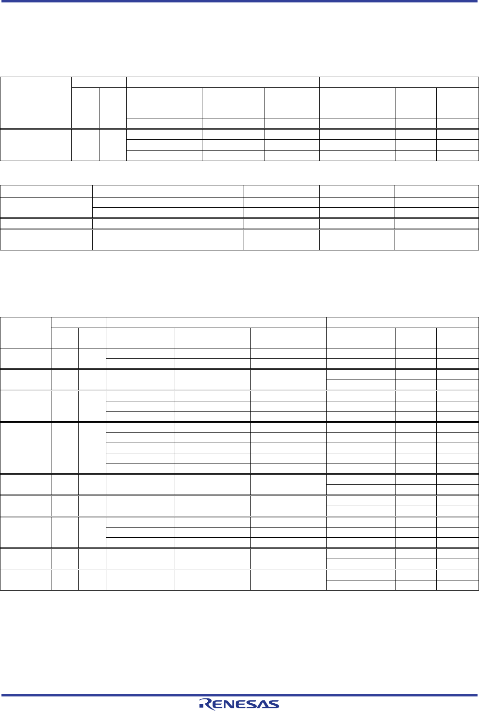
6.9 IRQ & Switch Configuration
Table 6-10 below details the function of the option links associated with IRQ & Switch Configuration.
Table 6-10: IRQ & Switch Configuration Option Links
Signal name
MCU
MCU Peripheral Selection
Destination Selection
Pin
Por
t
Signal Fit DNF
Interface
/Function
Fit DNF
P07 C7 P07
SW1
R207
-
SW1
-
R206
P07
-
-
P07
-
-
JP-UPSEL B5 P35 JP-UPSEL - -
J8.2
-
-
P35
-
-
P31 B4 P31
PMOD1-CS
R87
R85, R206
PMOD1.1
-
-
SSISCK0
R85
R87, R206
P31
-
-
SW1
R206
R87, R85
SW1
-
R207-
P30 A2 P30
PMOD1-MISO
J6 (2-3pin short)
R76, R80, R209
PMOD1.3
-
-
SW2
J6 (1-2pin short)
R76, R80, R209
SW2
-
-
EMU-RXD
R76
J6 (open), R80, R209
E1.11
-
-
AUDIO_MCLK
R80
J6 (open), R76, R209
P30
-
-
SERIAL-RXD
R209
J6 (open), R76, R80
U10. 2
-
R208
DIP-SW1 E8 P46 DIP-SW1 - -
SW4.2
-
-
P46
-
-
DIP-SW0 E9 P45 DIP-SW0 - -
SW4.1
-
-
P45
-
-
PB1
*1
J5 PB1
PMOD1-IRQ
J9 (2-3pin short)
-
PMOD1.7
-
-
PMOD2-IRQ
J9 (1-2pin short)
-
PMOD2.7
-
-
PB1
-
-
PB1
-
-
DIP-SW2 J6 PB0 DIP-SW2 - -
SW4.3
-
-
PB0
-
-
DIP-SW3 J8 PE4 DIP-SW3 - -
SW4.4
-
-
PE4
-
-
*1
: PMODx-IRQ can be multi-connection interrupts by mounting R130.