
User's Manual
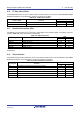
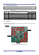
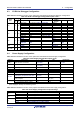
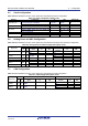
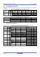
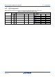
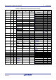
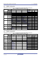
Table Of Contents
- 1. Overview
- 2. Power Supply
- 3. Board Layout
- 4. Connectivity
- 5. User Circuitry
- 6. Configuration
- 6.1 Modifying the RSSK
- 6.2 MCU Operating Modes
- 6.3 E1/E2 Lite Debugger Configuration
- 6.4 Power Supply Configuration
- 6.5 Clock Configuration
- 6.6 Analog Power and ADC Configuration
- 6.7 CAN Configuration
- 6.8 I2C & EEPROM Configuration
- 6.9 IRQ & Switch Configuration
- 6.10 LED Configuration
- 6.11 MCU Header Configuration
- 6.12 PMOD1 Configuration
- 6.13 PMOD2 Configuration
- 6.14 Bluetooth® Low Energy (BLE)
- 6.15 Serial Sound Interface (SSI)
- 6.16 Touch Interface Configuration
- 6.17 USB to Serial Configuration
- 6.18 USB Configuration
- 7. Code Development
- 8. Additional Information
- 9. Certification of Compliance
Renesas Solution Starter Kit for RX23W 6. Configuration
R20UT4446EG0102 Rev. 1.02 Page 25 of 41
Jun 22, 20
6.5 Clock Configuration
Table 6-5 below details the function of the option links associated with Clock Configuration.
Table 6-5: Clock Configuration Option Links
Reference
Configuration
Fit
DNF
Related Links
P47/CLKOUT_RF
Connect CLKOUT_RF to P36/EXTAL. R112, R89
R113, R108, R92,
R90, R97
X2
Connect CLKOUT_RF to MCU header.
R113
R112
P47
XTAL1_RF, XTAL2_RF
Connect 32MHz crystal (X1) to RX23W.
-
-
-
XTAL, EXTAL
Connect 8MHz crystal (X2) to RX23W.
R90, R97
R89, R96
-
Disconnect 8MHz crystal (X2) from RX23W and
connect to MCU header.
R89, R96, R108
R90, R97, R92,
R112
P36, P37
XCIN, XCOUT
Connect 32.768kHz crystal (X3) to RX23W.
R100, R99
R102
-
Disconnect X2 from RX23W.
R102
R100, R99
-
6.6 Analog Power and ADC Configuration
Table 6-6 below details the function of the option links associated with Analog Power and ADC Configuration.
Table 6-6: Analog Power and ADC Configuration Option Links
Signal name
MCU
MCU Peripheral Selection
Destination Selection
Pin
Port
Signal Fit DNF
Interface
/Function
Fit DNF
P07 C7 P07
SW1
R207
-
SW1
-
R206
P07
-
-
P07
-
-
RV1-ADC C9 P40 RV1-ADC - -
RV1
-
-
P40
-
-
VREFH0
C10
-
UC_VCC
R121
-
-
-
-
VREFL0
D10
-
GROUND
R124
-
-
-
-
AVCC0-1 B10 -
UC_VCC
R118
R127 or R128
-
-
-
Board_VCC
R128, R127
R118
-
-
-
AVSS0-1
A10
-
GROUND
R116
-
-
-
-
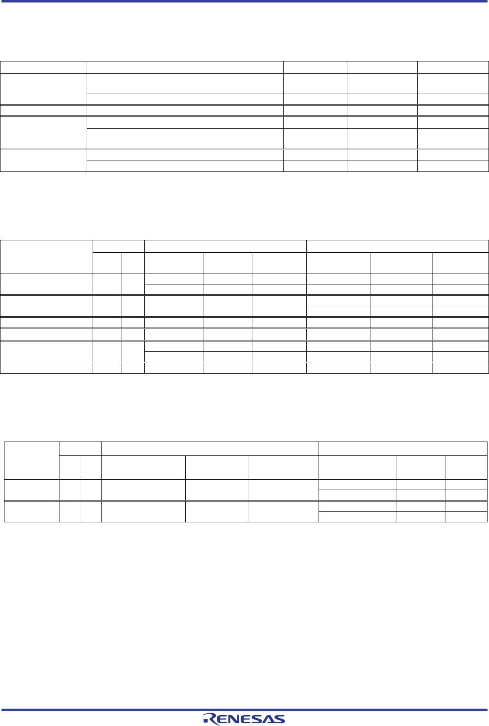
6.7 CAN Configuration
Table 6-7 below details the function of the option links associated with CAN Configuration.
Table 6-7: CAN Configuration Option Links
Signal name
MCU
MCU Peripheral Selection
Destination Selection
Pin
Port
Signal Fit DNF
Interface
/Function
Fit DNF
CAN0RX C2 P15 CAN0RX - -
U9.3
-
-
P15
-
-
CAN0TX C1 P14 CAN0TX - -
U7.3
-
-
P14
-
-