
User's Manual
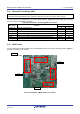
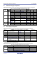
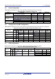
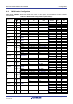
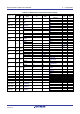
Table Of Contents
- 1. Overview
- 2. Power Supply
- 3. Board Layout
- 4. Connectivity
- 5. User Circuitry
- 6. Configuration
- 6.1 Modifying the RSSK
- 6.2 MCU Operating Modes
- 6.3 E1/E2 Lite Debugger Configuration
- 6.4 Power Supply Configuration
- 6.5 Clock Configuration
- 6.6 Analog Power and ADC Configuration
- 6.7 CAN Configuration
- 6.8 I2C & EEPROM Configuration
- 6.9 IRQ & Switch Configuration
- 6.10 LED Configuration
- 6.11 MCU Header Configuration
- 6.12 PMOD1 Configuration
- 6.13 PMOD2 Configuration
- 6.14 Bluetooth® Low Energy (BLE)
- 6.15 Serial Sound Interface (SSI)
- 6.16 Touch Interface Configuration
- 6.17 USB to Serial Configuration
- 6.18 USB Configuration
- 7. Code Development
- 8. Additional Information
- 9. Certification of Compliance
Renesas Solution Starter Kit for RX23W 5. User Circuitry
R20UT4446EG0102 Rev. 1.02 Page 22 of 41
Jun 22, 20
5.13 Bluetooth
®
Low Energy (BLE)
When running any Bluetooth
®
Low Energy (BLE) software, a unique Bluetooth Device address should be used. A
unique Renesas allocated Bluetooth Device address is attached to the PCB on the bottom side as a sticker.
The CPU board has one Bluetooth
®
Low Energy (BLE) interface. Table 5-13 below details the connected
devices, and their connections to the MCU.
Table 5-13: Bluetooth
®
Low Energy (BLE) Connections
BLE Signal Function
MCU
Port
Pin
CLKOUT_RF
RF clock output terminal
P47
F10
ANT
RF single transceiver RF single input / output terminal
ANT
K2
XTAL1_RF
32 MHz resonator connection terminal
XTAL1_RF
K7
XTAL2_RF
32 MHz resonator connection terminal
XTAL2_RF
K6
DCLOUT
Power supply output connection terminal for RF transceiver
*1
DCLOUT
K9
DCLIN_A
Power supply output connection terminal for RF transceiver
*1
DCLIN_A
G10
DCLIN_D
Power supply output connection terminal for RF transceiver
*1
DCLIN_D
H10
*1
: Circuit configuration used linear regulator when shipping the product.
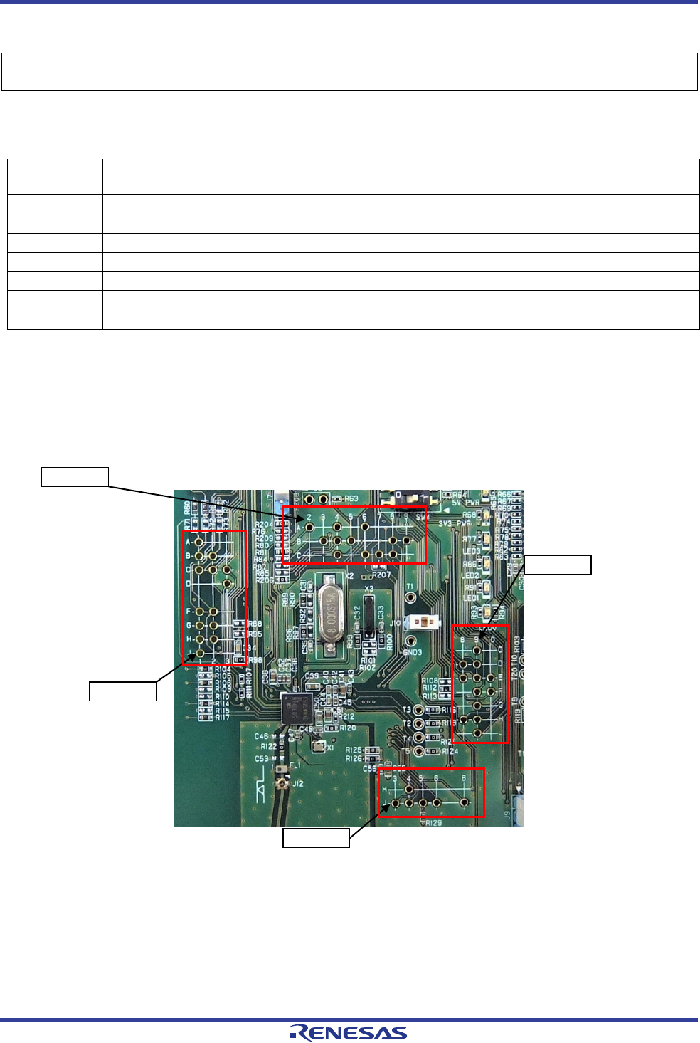
5.14 MCU Header
The CPU board has four MCU headers, and some RX23W pins are connected to the MCU headers. Figure 5-
2 shows an example of pin numbers.
Figure 5-2: Example of MCU Header pin numbers
A2 Pin
J3 Pin
J1 Pin
C9 Pin