
User's Manual
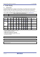
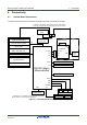
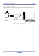
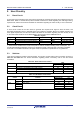
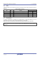
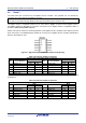
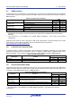
Table Of Contents
- 1. Overview
- 2. Power Supply
- 3. Board Layout
- 4. Connectivity
- 5. User Circuitry
- 6. Configuration
- 6.1 Modifying the RSSK
- 6.2 MCU Operating Modes
- 6.3 E1/E2 Lite Debugger Configuration
- 6.4 Power Supply Configuration
- 6.5 Clock Configuration
- 6.6 Analog Power and ADC Configuration
- 6.7 CAN Configuration
- 6.8 I2C & EEPROM Configuration
- 6.9 IRQ & Switch Configuration
- 6.10 LED Configuration
- 6.11 MCU Header Configuration
- 6.12 PMOD1 Configuration
- 6.13 PMOD2 Configuration
- 6.14 Bluetooth® Low Energy (BLE)
- 6.15 Serial Sound Interface (SSI)
- 6.16 Touch Interface Configuration
- 6.17 USB to Serial Configuration
- 6.18 USB Configuration
- 7. Code Development
- 8. Additional Information
- 9. Certification of Compliance
Renesas Solution Starter Kit for RX23W 5. User Circuitry
R20UT4446EG0102 Rev. 1.02 Page 20 of 41
Jun 22, 20
5.7 USB Serial Port
A USB serial port is implemented in a FT234XD and is connected to the RX23W Serial Communications
Interface (SCI) module. Connections between the USB to Serial converter and the microcontroller are listed in
Table 5-7 below.
Table 5-7: Serial Port Connections
Signal Name Function
MCU
Port
Pin
SERIAL-TXD
SCI8 Transmit Signal.
PC7
F1
SCI1 Transmit Signal.
*2
P26
B2
SERIAL-RXD
SCI8 Receive Signal.
PC6
F2
SCI1 Receive Signal.
*2
P30
A2
SERIAL-CTS
*1
Clear To Send.
PC4
G1
SERIAL-RTS
*1
Request To Send.
PC4
G1
*1
: This connection is a not available in the default CPU board configuration - refer to §6 for the required
modifications. CTS / RTS can be used exclusively. For details, refer to ‘RX23W Group User’s Manual:
Hardware’.
*2
: This connection is a not available in the default RSSK configuration - refer to §6 for the required
modifications.
USB serial driver made by FTDI is required for USB serial communication. Please download from the URL
below. Please contact FTDI for installation method of USB serial driver and questions.
https://www.ftdichip.com/Drivers/D2XX.htm
5.8 Controller Area Network (CAN)
A CAN transceiver IC is fitted to CPU board, and connected to the CAN MCU peripheral. For further details
regarding the CAN protocol and supported modes of operation, please Refer to ‘RX23W Group User’s
Manual: Hardware’. The connections for the CAN microcontroller signals are listed in Table 5-8 below.
Table 5-8: CAN Connections
CAN Signal Function
MCU
Port
Pin
CAN0TX
CAN Data Transmission.
P14
C1
CAN0RX
CAN Data Reception.
P15
C2
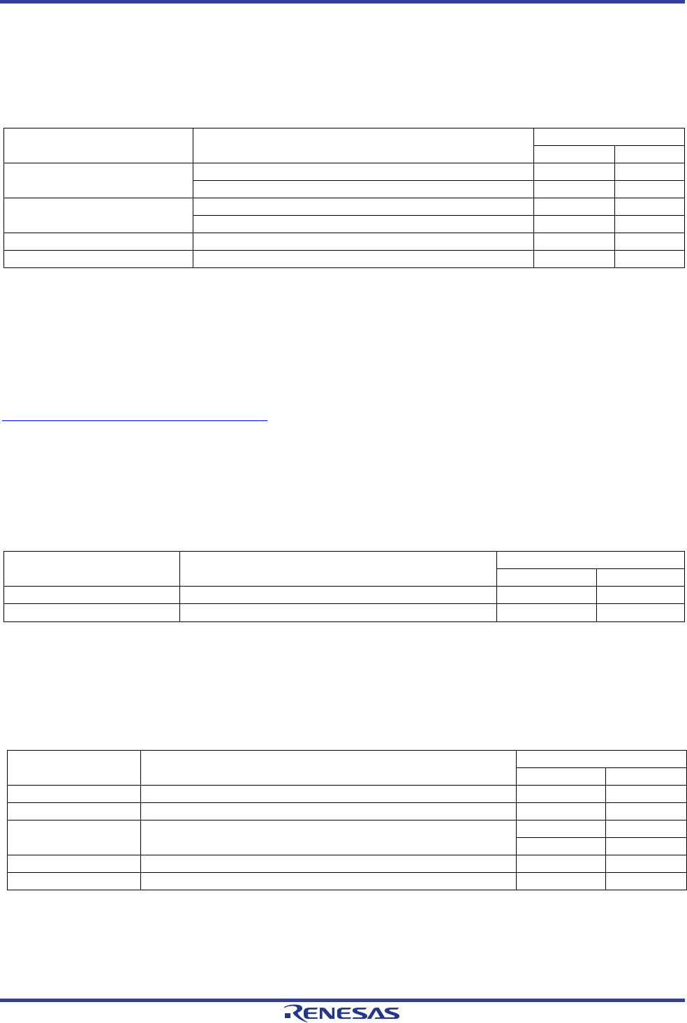
5.9 Universal Serial Bus (USB)
This CPU board is fitted with a USB Host socket (type A) and a Function socket (type Micro B). USB module
USB0 is connected to the Host and Function socket, and can operate as either a Host or Function device. The
connection for the USB0 module is shown in Table 5-9 below.
Table 5-9: USB0 Module Connections
USB Signal Function
MCU
Port
Pin
USB0-DP
D+ I/O pin of the USB on-chip transceiver
USB0_DP
E1
USB0-DM
D– I/O pin of the USB on-chip transceiver
USB0_DM
D1
USB0-VBUS USB cable connection monitor pin
PB5
*1
J4
P16
*2
C3
USB0-VBUSEN
VBUS (5V) supply enable signal for external power supply chip
P26
B2
USB0-OVRCURB
External overcurrent detection signals
P22
C4
*1
: Can't be used as USB-VBUS in USB boot mode.
*2
: This connection is a not available in the default RSSK configuration - refer to §6 for the required
modifications.