User’ s Manual 32 RX23W Group 32 Renesas Solution Starter Kit for RX23W User’s Manual RENESAS 32-Bit MCU RX Family / RX200 Series All information contained in these materials, including products and product specifications, represents information on the product at the time of publication and is subject to change by Renesas Electronics Corp. without notice. Please review the latest information published by Renesas Electronics Corp. through various means, including the Renesas Electronics Corp.
Notice 1. Descriptions of circuits, software and other related information in this document are provided only to illustrate the operation of semiconductor products and application examples. You are fully responsible for the incorporation or any other use of the circuits, software, and information in the design of your product or system.
General Precautions in the Handling of Microprocessing Unit and Microcontroller Unit Products The following usage notes are applicable to all Microprocessing unit and Microcontroller unit products from Renesas. For detailed usage notes on the products covered by this document, refer to the relevant sections of the document as well as any technical updates that have been issued for the products. 1.
Disclaimer By using this Renesas Solution Starter Kit (RSSK), the user accepts the following terms: The RSSK is not guaranteed to be error free, and the entire risk as to the results and performance of the RSSK is assumed by the User.
How to Use This Manual 1. Purpose and Target Readers This manual is designed to provide the user with an understanding of the CPU Board hardware functionality, and electrical characteristics. It is intended for users designing sample code on the CPU Board platform, using the many different incorporated peripheral devices. The manual comprises of an overview of the capabilities of the RSSK product, but does not intend to be a guide to embedded programming or hardware design.
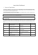
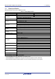
2. List of Abbreviations and Acronyms Abbreviation ADC BC BLE bps CAN CPU DAC DIP DMA DMAC DNF E1 / E2 Lite EEPROM EMC ESD GLCDC I2C (IIC) IRQ LCD LED LIN MCU MTU n/a (NA) n/c (NC) NMI OTG PC PDC PLL Full Form Analog-to-Digital Converter Battery Charging Bluetooth® Low Energy The Bluetooth® word mark and logos are registered trademarks owned be Bluetooth SIG, inc. and any use of such marks by Renesas Electronics Corporation is under license.
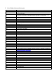
Table of Contents 1. Overview............................................................................................................................ 9 1.1 1.2 1.3 Purpose ...................................................................................................................................................... 9 Features ..................................................................................................................................................... 9 Board specification .
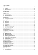
7.3 7.4 7.5 Mode Support .......................................................................................................................................... 34 Debugging Support .................................................................................................................................. 34 Address Space ......................................................................................................................................... 34 8. Additional Information ..........
1. Overview 1.1 Purpose This CPU Board is an evaluation tool for Renesas microcontrollers. This manual describes the technical details of the CPU Board hardware. 1.2 Features This RSSK provides an evaluation of the following features: • Renesas microcontroller programming • • User code debugging User circuitry such as switches, LEDs and a potentiometer Through the provided set of sample applications. The RSSK board contains all the circuitry required for microcontroller operation.
Renesas Solution Starter Kit for RX23W 1.3 1. Overview Board specification Board specification was shown in Table 1-1 below.
Renesas Solution Starter Kit for RX23W 2. Power Supply 2. Power Supply 2.1 Requirements This RSSK is supplied with an E1 debugger or E2 Lite debugger. The debugger is able to power the RSSK board with up to 200mA. When the RSSK is connected to another system, that system can supply power to the RSSK. This board has an optional centre-positive supply connector using a 2.0mm barrel power jack. This CPU board supports one external voltage input.
Renesas Solution Starter Kit for RX23W 3. Board Layout 3. Board Layout 3.1 Component Layout Figure 3-1 below shows the top component layout of the board.
Renesas Solution Starter Kit for RX23W 3.2 3. Board Layout Board Dimensions Figure 3-2 below gives the board dimensions and connector positions. All the through-hole connectors are on a common 2.54mm pitch grid for easy interfacing. Corners x 4 3.0 mm radius 10.00 Touch Interface (key) 10mm x 10mm MCU Headers x 4 2.54mm pitch above 7.00 10.00 above 7.00 above 7.00 7.50 Grid A2 5.00 7.50 MCU Header 22.86mm MCU Header 140mm Grid J1 15.24mm MCU Header 7.50 5.00 7.50 56.50 5.
Renesas Solution Starter Kit for RX23W 3.3 3. Board Layout Component Placement Figure 3-3 below shows placement of individual components on the top-side. Component types and values are shown on the board schematics.
Renesas Solution Starter Kit for RX23W 4. Connectivity 4. Connectivity 4.1 Internal Board Connections The diagram below shows the CPU board components and their connectivity to the MCU. In addition to DC PWR IN, VBUS (USB0 Function / USB to Serial Function) can be used as the power supply source for the board. DC PWR IN (5V) 5V USB0 (Host/Function) E1/E2 Lite Debug Interface 3.3V VBUS 5V Regulator IC 3.3V or 1.
Renesas Solution Starter Kit for RX23W 4.2 4. Connectivity Debugger Connections Figure 4-2 below shows the connections between the CPU board, E1/E2 Lite debugger and the host PC. LCD User Interface Cable USB Cable E1 Emulator or E2 Emulator Lite CPUBoard Host PC Figure 4-2: Debugger Connection Diagram R20UT4446EG0102 Rev. 1.
Renesas Solution Starter Kit for RX23W 5. User Circuitry 5. User Circuitry 5.1 Reset Circuit A reset control circuit is fitted to the CPU board to generate the required reset signal, and is triggered from the RES switch. Refer to ‘RX23W Group User’s Manual: Hardware’ for details regarding the reset signal timing requirements, and the CPU board schematics for information regarding the reset circuitry in use on the board. 5.
Renesas Solution Starter Kit for RX23W 5.4 5. User Circuitry LEDs There are 6 LEDs on the CPU board. The function of each LED, its colour, and its connections are shown in Table 5-4. Table 5-4: LED Connections LED 3V3 PWR 5V PWR LED0 LED1 LED2 LED3 5.5 Colour Green Green Green Orange Red Red Function Indicates the status of the Board_VCC power rail. Indicates the status of the Board_5V power rail. User operated LED. User operated LED. User operated LED. User operated LED.
Renesas Solution Starter Kit for RX23W 5.6 5. User Circuitry Pmod™ The CPU board has connectors for the Digilent Pmod™ interface. The operation can be checked by connecting the LCD module to the PMOD 2 connector. Care should be taken when installing the LCD module to ensure pins are not bent or damaged. The LCD module is vulnerable to electrostatic discharge (ESD); therefore appropriate ESD protection should be used. The Digilent Pmod™ Compatible headers use an SPI interface.
Renesas Solution Starter Kit for RX23W 5.7 5. User Circuitry USB Serial Port A USB serial port is implemented in a FT234XD and is connected to the RX23W Serial Communications Interface (SCI) module. Connections between the USB to Serial converter and the microcontroller are listed in Table 5-7 below. Table 5-7: Serial Port Connections Signal Name Function SCI8 Transmit Signal. SCI1 Transmit Signal. *2 SCI8 Receive Signal. SCI1 Receive Signal. *2 Clear To Send. Request To Send.
Renesas Solution Starter Kit for RX23W 5.10 5. User Circuitry I2C Bus (Inter-IC Bus) The RX23W features two I2C (Inter-IC Bus) interface modules. RIIC0 is connected to a 2Kbit EEPROM. Table 5-10 below details the connected device, and their connection to the MCU. Table 5-10: I2C Bus Connections I2C Bus signal E2P-SDA E2P-SCL 5.
Renesas Solution Starter Kit for RX23W 5.13 5. User Circuitry Bluetooth® Low Energy (BLE) When running any Bluetooth® Low Energy (BLE) software, a unique Bluetooth Device address should be used. A unique Renesas allocated Bluetooth Device address is attached to the PCB on the bottom side as a sticker. The CPU board has one Bluetooth® Low Energy (BLE) interface. Table 5-13 below details the connected devices, and their connections to the MCU.
Renesas Solution Starter Kit for RX23W 6. Configuration 6. Configuration 6.1 Modifying the RSSK This section lists the option links that are used to modify the way CPU board operates in order to access different configurations. Configurations are made by modifying link resistors or headers with movable jumpers or by configuration DIP switches A link resistor is a 0Ω surface mount resistor, which is used to short or isolate parts of a circuit.
Renesas Solution Starter Kit for RX23W 6.3 6. Configuration E1/E2 Lite Debugger Configuration Table 6-2 below details the function of the option links associated with E1/E2 Lite Debugger Configuration.
Renesas Solution Starter Kit for RX23W 6.5 6. Configuration Clock Configuration Table 6-5 below details the function of the option links associated with Clock Configuration. Table 6-5: Clock Configuration Option Links Reference Configuration Connect CLKOUT_RF to P36/EXTAL. P47/CLKOUT_RF R112, R89 Connect CLKOUT_RF to MCU header. R113 Connect 32MHz crystal (X1) to RX23W. Connect 8MHz crystal (X2) to RX23W. R90, R97 Disconnect 8MHz crystal (X2) from RX23W and R89, R96, R108 connect to MCU header.
Renesas Solution Starter Kit for RX23W 6.8 6. Configuration I2C & EEPROM Configuration Table 6-8 and Table 6-9 below detail the function of the option links associated with I2C & EEPROM Configuration. Table 6-8: I2C & EEPROM Configuration Option Links (1) MCU Port MCU Peripheral Selection Pin Signal name P17 B1 P17 E2P-SCL C3 P16 Fit E2P-SDA SSITXD0 E2P-SCL USB0-VBUS P16 DNF R61 R72 R200 R201 - R72 R61 R201 R200 - U3.5 P17 U3.6 J4.
Renesas Solution Starter Kit for RX23W 6.10 6. Configuration LED Configuration Table 6-11 below details the function of the option links associated with LED Configuration. Table 6-11: LED Configuration Option Links MCU Peripheral Selection Port MCU Pin Signal name LED3 E10 P44 LED3 - - LED2 D9 P43 LED2 - - LED1 D8 P42 LED1 - - LED0 C8 P41 LED0 - - R20UT4446EG0102 Rev. 1.02 Jun 22, 20 Signal Fit DNF Destination Selection Interface Fit /Function LED3.K P44 LED2.K P43 LED1.
Renesas Solution Starter Kit for RX23W 6.11 6. Configuration MCU Header Configuration Table 6-12 and Table 6-13 below details the function of the option links associated with MCU Header Configuration.
Renesas Solution Starter Kit for RX23W Port MCU Peripheral Selection LED1 D8 P42 LED1 - - LED0 C8 P41 LED0 - - PMOD1-IO3 J3 PB7 PMOD1-IO3 - - PB5 J4 PB5 R202 - - PMOD2-IO1 H4 PB3 PMOD2-IO1 - - PB1 J5 PMOD1-IRQ PB1 PMOD2-IRQ PB1 J9 (2-3pin short) J9 (1-2pin short) - - DIP-SW2 J6 PB0 DIP-SW2 - - - - F1 EMU-UB DSW-UB PC7 PC7 - - R203 - R208 R104 R105 R98 R88 R95 R105 R104 R88, R95 R98, R95 R88, R98 TS27 R106 R109 CON-PC3 R109 R106 TS30 R114 R110 CON-PC2
Renesas Solution Starter Kit for RX23W 6.12 6. Configuration PMOD1 Configuration Table 6-14 below details the function of the option links associated with PMOD1 Configuration.
Renesas Solution Starter Kit for RX23W 6.14 6. Configuration Bluetooth® Low Energy (BLE) Table 6-16 below details the function of the option links associated with Bluetooth® Low Energy (BLE) Configuration. Table 6-16: Bluetooth® Low Energy (BLE) Configuration Option Links 6.15 MCU Peripheral Selection Port ANT MCU Pin Signal name K2 - Signal Fit ANT DNF R122 - Destination Selection Interface Fit /Function FL1.
Renesas Solution Starter Kit for RX23W 6.17 6. Configuration USB to Serial Configuration Table 6-19 below details the function of the option links associated with USB to Serial Configuration. Table 6-19: USB to Serial Configuration Option Links MCU Peripheral Selection Port MCU Pin Signal name P26 B2 P26 P30 A2 P30 PC7 F1 PC7 PC6 F2 PC6 PC4 G1 PC4 6.
Renesas Solution Starter Kit for RX23W 6. Configuration Table 6-21 below details the function of the jumpers associated with the USB Configuration. Table 6-21: USB Configuration Jumper Option Links Reference J4 J5 Jumper Position Short Pin1-2 Short Pin2-3 All open Short Pin1-2 Short Pin2-3 All open Self-powered Bus-powered DO NOT SET. USB0 Function mode USB0 Host mode DO NOT SET.
Renesas Solution Starter Kit for RX23W 7. Code Development 7. Code Development 7.1 Overview For all code debugging using Renesas software tools, the CPU board must be connected to a PC via an E1/E20/E2 Lite debugger. An E1/E2 Lite debugger is supplied with this RSSK product. For further information regarding the debugging capabilities of the E1/E20/E2 Lite debuggers, refer to 'E1/E20 Emulator, E2 Emulator Lite - Additional Document for User's Manual' (R20UT0399EJ). 7.
Renesas Solution Starter Kit for RX23W 8. Additional Information 8. Additional Information Technical Support For information about the RX23W Group microcontrollers refer to ‘RX23W Group User’s Manual: Hardware’. For information about the RX assembly language, refer to ‘RX Family User’s Manual: Software’.
Renesas Solution Starter Kit for RX23W 9. Certification of Compliance 9. Certification of Compliance The Renesas Solution Starter kit for RX23W has obtained certificates of compliance with the laws and regulations stated below. Since the use of this product in countries and regions that require compliance with other regulations may lead to the violation of the laws; confirm the regulations of such countries in which the product is to be used.
Renesas Solution Starter Kit for RX23W 9. Certification of Compliance FCC/ISED Regulatory FCC ID: 2AEMXRX23WSKB85 This device complies with part 15 of the FCC Rules. Operation is subject to the following two conditions: (1) This device may not cause harmful interference, and (2) this device must accept any interference received, including interference that may cause undesired operation.
Renesas Solution Starter Kit for RX23W 9. Certification of Compliance China SRRC 1. 使用频率:2.4 - 2.4835 GHz 等效全向辐射功率(EIRP): 天线增益<10dBi 时:≤100 mW 或≤20 dBm 最大功率谱密度: 天线增益<10dBi 时:≤20 dBm / MHz(EIRP) 载频容限:20 ppm 帯外发射功率(在 2.4-2.4835GHz 頻段以外) ≤-80 dBm / Hz (EIRP) 杂散发射(辐射)功率(对应载波±2.5 倍信道带宽以外): ≤-36 dBm / 100 kHz (30 - 1000 MHz) ≤-33 dBm / 100 kHz (2.4 - 2.4835 GHz) ≤-40 dBm / 1 MHz (3.4 - 3.53 GHz) ≤-40 dBm / 1 MHz (5.725 - 5.85 GHz) ≤-30 dBm / 1 MHz (其它 1 - 12.75 GHz) 2.
REVISION HISTORY Rev. 1.00 1.01 1.02 Date Aug.30.19 Mar.25.20 RX23W Group Renesas Solution Starter Kit for RX23W User’s Manual Description Page Summary 36 First Edition issued 9 Added contents of Certification of Compliance May.13.20 37 9.1 Change authentication number of Japan’s Type certification 9.1 Updated contents of FCC/ISED Regulatory Jun.22.20 36 9.1 Replace HVIN and PMN with tables in FCC / ISED Regulatory 9.1 Added the certification number of Korea Radio Regulations 36, 38 9.
RX23W Group Renesas Solution Starter Kit for RX23W User’s Manual Publication Date: Rev.1.00 Rev.1.
RX23W Group R20UT4446EG0102