
Users Manual
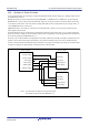
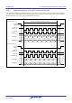
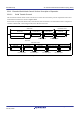
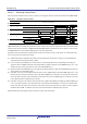
Table Of Contents
- 34. IrDA Interface
- 35. I2C-bus Interface (RIICa)
- 35.1 Overview
- 35.2 Register Descriptions
- 35.2.1 I2C-bus Control Register 1 (ICCR1)
- 35.2.2 I2C-bus Control Register 2 (ICCR2)
- 35.2.3 I2C-bus Mode Register 1 (ICMR1)
- 35.2.4 I2C-bus Mode Register 2 (ICMR2)
- 35.2.5 I2C-bus Mode Register 3 (ICMR3)
- 35.2.6 I2C-bus Function Enable Register (ICFER)
- 35.2.7 I2C-bus Status Enable Register (ICSER)
- 35.2.8 I2C-bus Interrupt Enable Register (ICIER)
- 35.2.9 I2C-bus Status Register 1 (ICSR1)
- 35.2.10 I2C-bus Status Register 2 (ICSR2)
- 35.2.11 Slave Address Register Ly (SARLy) (y = 0 to 2)
- 35.2.12 Slave Address Register Uy (SARUy) (y = 0 to 2)
- 35.2.13 I2C-bus Bit Rate Low-Level Register (ICBRL)
- 35.2.14 I2C-bus Bit Rate High-Level Register (ICBRH)
- 35.2.15 I2C-bus Transmit Data Register (ICDRT)
- 35.2.16 I2C-bus Receive Data Register (ICDRR)
- 35.2.17 I2C-bus Shift Register (ICDRS)
- 35.3 Operation
- 35.4 SCL Synchronization Circuit
- 35.5 SDA Output Delay Function
- 35.6 Digital Noise Filters
- 35.7 Address Match Detection
- 35.8 Automatic Low-Hold Function for SCL
- 35.9 Arbitration-Lost Detection Functions
- 35.10 Start Condition/Restart Condition/Stop Condition Generating Function
- 35.11 Bus Hanging
- 35.12 SMBus Operation
- 35.13 Interrupt Sources
- 35.14 Initialization of Registers and Functions When a Reset is Applied or a Condition is Detected
- 35.15 Event Link Function (Output)
- 35.16 Usage Notes
- 36. CAN Module (RSCAN)

R01UH0823EJ0110 Rev.1.10 Page 1081 of 1852
Nov 30, 2020
RX23W Group 33. Serial Communications Interface (SCIg, SCIh)
33.8.1 States of Pins in Master and Slave Modes
The direction (input or output) of pins for the simple SPI mode interface differs according to whether the device is a
master (SCR.CKE[1:0] = 00b or 01b and SPMR.MSS = 0) or slave (SCR.CKE[1:0] = 10b or 11b and SPMR.MSS = 1).
Table 33.29 lists the states of pins according to the mode and the level on the SSn# pin.
Note 1. When there is only a single master (SPMR.SSE = 0), transfer is possible regardless of the input level on the SSn# pin (this is
equivalent to input of a high level on the SSn# pin). Since the SSn# pin function is not required, the pin is available for other
purposes.
Note 2. The SMOSIn pin output is in the high-impedance state when serial transmission is disabled (SCR.TE bit = 0).
Note 3. The SCKn pin output is in the high-impedance state when serial transmission is disabled (SCR.TE and RE bits = 00b) in a multi-
master configuration (SPMR.SSE = 1).
33.8.2 SS Function in Master Mode
Setting the SCR.CKE[1:0] bits to 00b and the SPMR.MSS bit to 0 selects master operation. The SSn# pin is not used in
single-master configurations (SPMR.SSE = 0), so transmission or reception can proceed regardless of the value of the
SSn# pin.
When the level on the SSn# pin is high in a multi-master configuration (SPMR.SSE = 1), a master device outputs clock
signals from the SCKn pin before starting transmission or reception to indicate that there are no other masters or another
master is performing reception or transmission. When the level on the SSn# pin is low in a multi-master configuration
(SPMR.SSE = 1), there are other masters, and this indicates that transmission or reception is in progress. At this time the
SMOSIn output and SCKn pins will be placed in the high-impedance state and starting transmission or reception will not
be possible. Furthermore, the value of the SPMR.MFF bit will be 1, indicating a mode fault error. In a multi-master
configuration, start error processing by reading SPMR.MFF flag. Also, even if a mode fault error occurs while
transmission or reception is in progress, transmission or reception will not be stopped, but the SMOSIn and SCKn pin
output will be placed in the high-impedance state after the completion of the transfer.
Control a general port pin to produce the SS output signal from the master.
33.8.3 SS Function in Slave Mode
Setting the SCR.CKE[1:0] bits to 10b and the SPMR.MSS bit to 1 selects slave operation. When the level on the SSn#
pin is high, the SMISOn output pin will be in the high-impedance state and clock input through the SCKn pin will be
ignored. When the level on the SSn# pin is low, clock input through the SCKn pin will be effective and transmission or
reception can proceed.
If the input on the SSn# pin changes from low to high level during transmission or reception, the SMISOn output pin will
be placed in the high-impedance state. Meanwhile, the internal processing for transmission or reception will continue at
the rate of the clock input through the SCKn pin until processing for the character currently being transmitted or received
is completed, after which it stops. At that time, an interrupt (the appropriate one from among TXI, RXI, and TEI) will be
generated.
Table 33.29 States of Pins by Mode and Input Level on the SSn# Pin
Mode Input on SSn# Pin State of SMOSIn Pin State of SMISOn Pin State of SCKn Pin
Master mode*
1
High level
(transfer can proceed)
Output for data
transmission*
2
Input for received data Clock output*
3
Low level
(transfer cannot proceed)
High-impedance Input for received data
(but disabled)
High-impedance
Slave mode High level
(transfer cannot proceed)
Input for received data
(but disabled)
High-impedance Clock input
(but disabled)
Low level
(transfer can proceed)
Input for received data Output for data
transmission
Clock input