
Users Manual
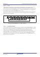
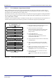
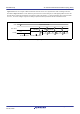
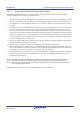
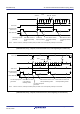
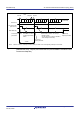
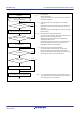
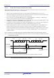
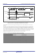
Table Of Contents
- 34. IrDA Interface
- 35. I2C-bus Interface (RIICa)
- 35.1 Overview
- 35.2 Register Descriptions
- 35.2.1 I2C-bus Control Register 1 (ICCR1)
- 35.2.2 I2C-bus Control Register 2 (ICCR2)
- 35.2.3 I2C-bus Mode Register 1 (ICMR1)
- 35.2.4 I2C-bus Mode Register 2 (ICMR2)
- 35.2.5 I2C-bus Mode Register 3 (ICMR3)
- 35.2.6 I2C-bus Function Enable Register (ICFER)
- 35.2.7 I2C-bus Status Enable Register (ICSER)
- 35.2.8 I2C-bus Interrupt Enable Register (ICIER)
- 35.2.9 I2C-bus Status Register 1 (ICSR1)
- 35.2.10 I2C-bus Status Register 2 (ICSR2)
- 35.2.11 Slave Address Register Ly (SARLy) (y = 0 to 2)
- 35.2.12 Slave Address Register Uy (SARUy) (y = 0 to 2)
- 35.2.13 I2C-bus Bit Rate Low-Level Register (ICBRL)
- 35.2.14 I2C-bus Bit Rate High-Level Register (ICBRH)
- 35.2.15 I2C-bus Transmit Data Register (ICDRT)
- 35.2.16 I2C-bus Receive Data Register (ICDRR)
- 35.2.17 I2C-bus Shift Register (ICDRS)
- 35.3 Operation
- 35.4 SCL Synchronization Circuit
- 35.5 SDA Output Delay Function
- 35.6 Digital Noise Filters
- 35.7 Address Match Detection
- 35.8 Automatic Low-Hold Function for SCL
- 35.9 Arbitration-Lost Detection Functions
- 35.10 Start Condition/Restart Condition/Stop Condition Generating Function
- 35.11 Bus Hanging
- 35.12 SMBus Operation
- 35.13 Interrupt Sources
- 35.14 Initialization of Registers and Functions When a Reset is Applied or a Condition is Detected
- 35.15 Event Link Function (Output)
- 35.16 Usage Notes
- 36. CAN Module (RSCAN)

R01UH0823EJ0110 Rev.1.10 Page 1038 of 1852
Nov 30, 2020
RX23W Group 33. Serial Communications Interface (SCIg, SCIh)
Figure 33.15 Example of SCI Operation for Serial Reception in Asynchronous Mode (2)
(When RTS Function is Used) (Example with 8-Bit Data, Parity, 1 Stop Bit)
Table 33.28 lists the states of the status flags in the SSR register and receive data handling when a receive error is
detected.
If a receive error is detected, an ERI interrupt request is generated but an RXI interrupt request is not generated. Data
reception cannot be resumed while the receive error flag is 1. Accordingly, set the ORER, FER, and PER flags to 0
before resuming reception. Moreover, be sure to read the RDR (or the RDRL) register during overrun error processing.
When a reception is forcibly terminated by setting the SCR.RE bit to 0 during operation, read the RDR (or the RDRL)
register because received data which has not yet been read may be left in the RDR (or the RDRL) register.
Figure 33.16 and Figure 33.17 show samples of flowcharts for serial data reception.
Note 1. Read data not in the RDR register but in the RDRH and RDRL registers when 9-bit data length is selected.
Table 33.28 Status Flags in the SSR Register and Receive Data Handling
Status Flags in the SSR Register
Receive Data Receive Error TypeORER FER PER
1 0 0 Lost Overrun error
010Transferred to the RDR register*
1
Framing error
001Transferred to the RDR register*
1
Parity error
1 1 0 Lost Overrun error + framing error
1 0 1 Lost Overrun error + parity error
011Transferred to the RDR register*
1
Framing error + parity error
1 1 1 Lost Overrun error + framing error + parity error
RXI interrupt flag
(IRn in ICU*
1
)
SSR.FER flag
0
1 frame
D0
D7 0/1 1 0 D0 D7
0/1 0
Data Data
Parity
bit
Stop
bit
Start bit
Parity
bit
Stop
bit
Start bit
Idle state
(mark state)
ERI interrupt request
generated by framing error
RXI interrupt
request
generated
RDR data read in RXI interrupt
handling routine
RTSn# pin
Error flag is cleared
0D0
Data
Start bit
Note 1. Refer to section 15, Interrupt Controller (ICUb) for details on the corresponding interrupt vector number.