
Users Manual
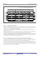
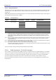
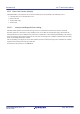
Table Of Contents
- 34. IrDA Interface
- 35. I2C-bus Interface (RIICa)
- 35.1 Overview
- 35.2 Register Descriptions
- 35.2.1 I2C-bus Control Register 1 (ICCR1)
- 35.2.2 I2C-bus Control Register 2 (ICCR2)
- 35.2.3 I2C-bus Mode Register 1 (ICMR1)
- 35.2.4 I2C-bus Mode Register 2 (ICMR2)
- 35.2.5 I2C-bus Mode Register 3 (ICMR3)
- 35.2.6 I2C-bus Function Enable Register (ICFER)
- 35.2.7 I2C-bus Status Enable Register (ICSER)
- 35.2.8 I2C-bus Interrupt Enable Register (ICIER)
- 35.2.9 I2C-bus Status Register 1 (ICSR1)
- 35.2.10 I2C-bus Status Register 2 (ICSR2)
- 35.2.11 Slave Address Register Ly (SARLy) (y = 0 to 2)
- 35.2.12 Slave Address Register Uy (SARUy) (y = 0 to 2)
- 35.2.13 I2C-bus Bit Rate Low-Level Register (ICBRL)
- 35.2.14 I2C-bus Bit Rate High-Level Register (ICBRH)
- 35.2.15 I2C-bus Transmit Data Register (ICDRT)
- 35.2.16 I2C-bus Receive Data Register (ICDRR)
- 35.2.17 I2C-bus Shift Register (ICDRS)
- 35.3 Operation
- 35.4 SCL Synchronization Circuit
- 35.5 SDA Output Delay Function
- 35.6 Digital Noise Filters
- 35.7 Address Match Detection
- 35.8 Automatic Low-Hold Function for SCL
- 35.9 Arbitration-Lost Detection Functions
- 35.10 Start Condition/Restart Condition/Stop Condition Generating Function
- 35.11 Bus Hanging
- 35.12 SMBus Operation
- 35.13 Interrupt Sources
- 35.14 Initialization of Registers and Functions When a Reset is Applied or a Condition is Detected
- 35.15 Event Link Function (Output)
- 35.16 Usage Notes
- 36. CAN Module (RSCAN)

R01UH0823EJ0110 Rev.1.10 Page 1197 of 1852
Nov 30, 2020
RX23W Group 35. I
2
C-bus Interface (RIICa)
35.16 Usage Notes
35.16.1 Setting Module Stop Function
Module stop state can be entered or released using module stop control register B (MSTPCRB). The initial setting is for
operation of the RIIC to be stopped. RIIC register access is enabled by releasing the module stop state.
For details on module stop control register B, refer to
section 11, Low Power Consumption.
35.16.2 Notes on Starting Transfer
If the IR flag corresponding to the RIIC interrupt is 1 when transfer is started (ICCR1.ICE bit is 1), follow the procedure
below to clear interrupts before enabling operations. Starting transfer with the IR flag set to 1 while the ICCR1.ICE bit is
1 leads to an interrupt request being internally retained after transfer starts, and this can lead to unanticipated behavior of
the IR flag.
1. Confirm that the ICCR1.ICE bit is 0.
2. Set the relevant interrupt enable bits (ICIER.TIE, etc.) on the peripheral function side to 0.
3. Read the relevant interrupt enable bits (ICIER.TIE, etc.) on the peripheral function side and confirm that its value is 0.
4. Set the IR flag to 0.