
Users Manual
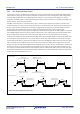
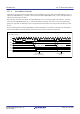
Table Of Contents
- 34. IrDA Interface
- 35. I2C-bus Interface (RIICa)
- 35.1 Overview
- 35.2 Register Descriptions
- 35.2.1 I2C-bus Control Register 1 (ICCR1)
- 35.2.2 I2C-bus Control Register 2 (ICCR2)
- 35.2.3 I2C-bus Mode Register 1 (ICMR1)
- 35.2.4 I2C-bus Mode Register 2 (ICMR2)
- 35.2.5 I2C-bus Mode Register 3 (ICMR3)
- 35.2.6 I2C-bus Function Enable Register (ICFER)
- 35.2.7 I2C-bus Status Enable Register (ICSER)
- 35.2.8 I2C-bus Interrupt Enable Register (ICIER)
- 35.2.9 I2C-bus Status Register 1 (ICSR1)
- 35.2.10 I2C-bus Status Register 2 (ICSR2)
- 35.2.11 Slave Address Register Ly (SARLy) (y = 0 to 2)
- 35.2.12 Slave Address Register Uy (SARUy) (y = 0 to 2)
- 35.2.13 I2C-bus Bit Rate Low-Level Register (ICBRL)
- 35.2.14 I2C-bus Bit Rate High-Level Register (ICBRH)
- 35.2.15 I2C-bus Transmit Data Register (ICDRT)
- 35.2.16 I2C-bus Receive Data Register (ICDRR)
- 35.2.17 I2C-bus Shift Register (ICDRS)
- 35.3 Operation
- 35.4 SCL Synchronization Circuit
- 35.5 SDA Output Delay Function
- 35.6 Digital Noise Filters
- 35.7 Address Match Detection
- 35.8 Automatic Low-Hold Function for SCL
- 35.9 Arbitration-Lost Detection Functions
- 35.10 Start Condition/Restart Condition/Stop Condition Generating Function
- 35.11 Bus Hanging
- 35.12 SMBus Operation
- 35.13 Interrupt Sources
- 35.14 Initialization of Registers and Functions When a Reset is Applied or a Condition is Detected
- 35.15 Event Link Function (Output)
- 35.16 Usage Notes
- 36. CAN Module (RSCAN)

R01UH0823EJ0110 Rev.1.10 Page 1178 of 1852
Nov 30, 2020
RX23W Group 35. I
2
C-bus Interface (RIICa)
35.8 Automatic Low-Hold Function for SCL
35.8.1 Function to Prevent Wrong Transmission of Transmit Data
If the shift register (ICDRS) is empty when data have not been written to the I
2
C-bus transmit data register (ICDRT) with
the RIIC in transmission mode (ICCR2.TRS bit is 1), the SCL0 line is automatically held low over the intervals shown
below. This low period is extended until data for transmission have been written, which prevents the unintended
transmission of erroneous data.
Master transmit mode
• Low period after a start condition or restart condition is generated
• Low period between the ninth clock pulse of one transfer and the first clock pulse of the next
Slave transmit mode
• Low period between the ninth clock pulse of one transfer and the first clock pulse of the next
Figure 35.30 Automatic Low-Hold Operation in Transmit Mode
8
R
9
ACK
TDRE
AASy
TRS
BBSY
RDRF
S 1 234567 234567 8 9
ACK
23
[Master transmit mode]
[Slave transmit mode]
TDRE
AASy
TRS
BBSY
RDRF
S 234567 234567 8 9
ACK
8
W
9
ACK
21 1 1
11
Data (DATA 1)
7-bit slave address
Data (DATA 1)
7-bit slave address
Write data to ICDRT register
(DATA 1)
Write data to ICDRT register
(DATA 2)
Write data to ICDRT register
(DATA 2)
Write data to ICDRT register
(DATA 1)
Write data to ICDRT register
(7-bit address + W)
Transmit data (7-bit address + W) Transmit data (DATA 1) Transmit data (DATA 2)
Transmit data (DATA 1)
Address match
Automatic low-hold (to prevent wrong transmission)
Automatic low-hold
(to prevent wrong
transmission)
Automatic low-hold
(to prevent wrong
transmission)
Automatic low-hold (to prevent wrong transmission)Automatic low-hold (to prevent wrong transmission)
Transmit data (DATA 2)
SCL0
SDA0
SCL0
SDA0