
Users Manual
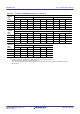
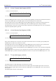
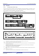
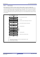
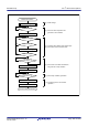
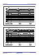
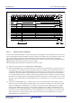
Table Of Contents
- 34. IrDA Interface
- 35. I2C-bus Interface (RIICa)
- 35.1 Overview
- 35.2 Register Descriptions
- 35.2.1 I2C-bus Control Register 1 (ICCR1)
- 35.2.2 I2C-bus Control Register 2 (ICCR2)
- 35.2.3 I2C-bus Mode Register 1 (ICMR1)
- 35.2.4 I2C-bus Mode Register 2 (ICMR2)
- 35.2.5 I2C-bus Mode Register 3 (ICMR3)
- 35.2.6 I2C-bus Function Enable Register (ICFER)
- 35.2.7 I2C-bus Status Enable Register (ICSER)
- 35.2.8 I2C-bus Interrupt Enable Register (ICIER)
- 35.2.9 I2C-bus Status Register 1 (ICSR1)
- 35.2.10 I2C-bus Status Register 2 (ICSR2)
- 35.2.11 Slave Address Register Ly (SARLy) (y = 0 to 2)
- 35.2.12 Slave Address Register Uy (SARUy) (y = 0 to 2)
- 35.2.13 I2C-bus Bit Rate Low-Level Register (ICBRL)
- 35.2.14 I2C-bus Bit Rate High-Level Register (ICBRH)
- 35.2.15 I2C-bus Transmit Data Register (ICDRT)
- 35.2.16 I2C-bus Receive Data Register (ICDRR)
- 35.2.17 I2C-bus Shift Register (ICDRS)
- 35.3 Operation
- 35.4 SCL Synchronization Circuit
- 35.5 SDA Output Delay Function
- 35.6 Digital Noise Filters
- 35.7 Address Match Detection
- 35.8 Automatic Low-Hold Function for SCL
- 35.9 Arbitration-Lost Detection Functions
- 35.10 Start Condition/Restart Condition/Stop Condition Generating Function
- 35.11 Bus Hanging
- 35.12 SMBus Operation
- 35.13 Interrupt Sources
- 35.14 Initialization of Registers and Functions When a Reset is Applied or a Condition is Detected
- 35.15 Event Link Function (Output)
- 35.16 Usage Notes
- 36. CAN Module (RSCAN)

R01UH0823EJ0110 Rev.1.10 Page 1158 of 1852
Nov 30, 2020
RX23W Group 35. I
2
C-bus Interface (RIICa)
Figure 35.9 Master Transmit Operation Timing (3)
35.3.4 Master Receive Operation
In master receive operation, the RIIC as a master device generates clock signals, receives data from the slave device, and
returns acknowledgments. Because the RIIC must start by sending a slave address to the corresponding slave device, this
part of the procedure is performed in master transmit mode, but the subsequent steps are in master receive mode.
Figure 35.10 and Figure 35.11 show examples of usage of master reception (7-bit address format) and Figure 35.12 to
Figure 35.14 show the timing of operations in master reception.
The following describes the procedure and operations for master reception.
(1) Initial settings. For details, refer to
section 35.3.2, Initial Settings.
(2) Read the ICCR2.BBSY flag to check that the bus is open, and then set the ICCR2.ST bit to 1 (requests to generate a
start condition). Upon receiving the request, the RIIC generates a start condition. When the RIIC detects the start
condition, the BBSY flag and the ICSR2.START flag are automatically set to 1 and the ST bit is automatically set to
0. At this time, if the start condition is detected and the levels for the SDA output and the levels on the SDA0 line
have matched while the ST bit is 1, the RIIC recognizes that generating of the start condition as requested by the ST
bit has been successfully completed, and bits MST and TRS in the ICCR2 register are automatically set to 1, placing
the RIIC in master transmit mode. The ICSR2.TDRE flag is also automatically set to 1 in response to setting of the
TRS bit to 1.
(3) Check that the ICSR2.TDRE flag is 1, and then write the value for transmission (the first byte indicates the slave
address and value of the R/W# bit) to the ICDRT register. Once the data for transmission are written to the ICDRT
register, the TDRE flag is automatically set to 0, the data are transferred from the ICDRT register to the ICDRS
register, and the TDRE flag is again set to 1. Once the byte containing the slave address and R/W# bit has been
transmitted, the value of the ICCR2.TRS bit is automatically updated to select transmit or receive mode in accord
with the value of the transmitted R/W# bit. If the value of the R/W# bit was 1, the TRS bit is set to 0 on the rising
edge of the ninth SCL, placing the RIIC in master receive mode. At this time, the TDRE flag is set to 0 and the
ICSR2.RDRF flag is automatically set to 1.
DATA n-1
DATA n
DATA n
2
b6
4
b4
5
b3
6
b2
7
b1
3
b5
8
b0
1
b7
2
b6
4
b4
5
b3
6
b2
7
b1
3
b5
8
b0
8
b0
1
b7
7
b1
9
DATA n-1
DATA n-1 DATA nDATA n-2
99
XXXX (Initial value/final receive data)
[5]
Write 1
to SP bit
[4]
Clear
STOP flag
[7]
P
Write data to ICDRT register
(Final transmit data [DATA n])
0 (ACK)0 (ACK)
0 (ACK)
DATA n-2
TDRE
MST
TRS
BBSY
TEND
STOP
ICDRT
ICDRS
SP
RDRF
ICDRR
ACKBT
ACKBR
A/NAACK
X (ACK/NACK)
Transmit data (DATA n)
ACK
Transmit data (DATA n-1)
SCL0
SDA0