
Users Manual
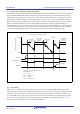
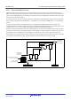

Table Of Contents
- 34. IrDA Interface
- 35. I2C-bus Interface (RIICa)
- 35.1 Overview
- 35.2 Register Descriptions
- 35.2.1 I2C-bus Control Register 1 (ICCR1)
- 35.2.2 I2C-bus Control Register 2 (ICCR2)
- 35.2.3 I2C-bus Mode Register 1 (ICMR1)
- 35.2.4 I2C-bus Mode Register 2 (ICMR2)
- 35.2.5 I2C-bus Mode Register 3 (ICMR3)
- 35.2.6 I2C-bus Function Enable Register (ICFER)
- 35.2.7 I2C-bus Status Enable Register (ICSER)
- 35.2.8 I2C-bus Interrupt Enable Register (ICIER)
- 35.2.9 I2C-bus Status Register 1 (ICSR1)
- 35.2.10 I2C-bus Status Register 2 (ICSR2)
- 35.2.11 Slave Address Register Ly (SARLy) (y = 0 to 2)
- 35.2.12 Slave Address Register Uy (SARUy) (y = 0 to 2)
- 35.2.13 I2C-bus Bit Rate Low-Level Register (ICBRL)
- 35.2.14 I2C-bus Bit Rate High-Level Register (ICBRH)
- 35.2.15 I2C-bus Transmit Data Register (ICDRT)
- 35.2.16 I2C-bus Receive Data Register (ICDRR)
- 35.2.17 I2C-bus Shift Register (ICDRS)
- 35.3 Operation
- 35.4 SCL Synchronization Circuit
- 35.5 SDA Output Delay Function
- 35.6 Digital Noise Filters
- 35.7 Address Match Detection
- 35.8 Automatic Low-Hold Function for SCL
- 35.9 Arbitration-Lost Detection Functions
- 35.10 Start Condition/Restart Condition/Stop Condition Generating Function
- 35.11 Bus Hanging
- 35.12 SMBus Operation
- 35.13 Interrupt Sources
- 35.14 Initialization of Registers and Functions When a Reset is Applied or a Condition is Detected
- 35.15 Event Link Function (Output)
- 35.16 Usage Notes
- 36. CAN Module (RSCAN)

R01UH0823EJ0110 Rev.1.10 Page 1105 of 1852
Nov 30, 2020
RX23W Group 33. Serial Communications Interface (SCIg, SCIh)
33.13 Event Linking
By employing interrupt request signals as event signals, SCI5 is able to provide linked operation through the event link
controller (ELC) for modules selected in advance.
Event signals can be output regardless of the values of the corresponding interrupt request enable bits.
(1) Error (receive error, error signal detected) event output
• Indicates abnormal termination due to a parity error during reception in asynchronous mode.
• Indicates abnormal termination due to a framing error during reception in asynchronous mode.
• Indicates abnormal termination due to an overrun error during reception.
• Indicates detection of the error signal during transmission in smart card interface mode.
(2) Receive data full event output
• Indicates that received data have been set in the receive data register (RDR or RDRL).
• Indicates that ACK has been detected if the SIMR2.IICINTM bit is 0 in simple I
2
C mode.
• Indicates that the 8th-bit SSCL5 falling edge has been detected if the SIMR2.IICINTM bit is 1 in simple I
2
C mode.
• When the SIMR2.IICINTM bit is 1 during master transmission in simple I
2
C mode, set the event link controller
(ELC) so that receive data full events are not used.
(3) Transmit data empty event output
• Indicates that the SCR.TE bit has been changed from 0 to 1.
• Indicates that transmit data have been transferred from the transmit data register (TDR or TDRL) to the transmit
shift register (TSR).
• Indicates that transmission has been completed in smart card interface mode.
• Indicates that NACK has been detected if the SIMR2.IICINTM bit is 0 in simple I
2
C mode.
• Indicates that the ninth-bit SSCL5 falling edge has been detected if the SIMR2.IICINTM bit is 1 in simple I
2
C
mode.
(4) Transmit end event output
• Indicates the completion of transmission.
• Indicates that the starting condition, resumption condition, or termination condition has been generated in simple
I
2
C mode.