
Users Manual
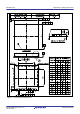
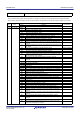
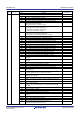
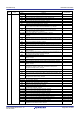
Table Of Contents
- 45. 12-Bit D/A Converter (R12DAA)
- 46. Temperature Sensor (TEMPSA)
- 47. Comparator B (CMPBa)
- 47.1 Overview
- 47.2 Register Descriptions
- 47.2.1 Comparator B1 Control Register 1 (CPB1CNT1)
- 47.2.2 Comparator B1 Control Register 2 (CPB1CNT2)
- 47.2.3 Comparator B1 Flag Register (CPB1FLG)
- 47.2.4 Comparator B1 Interrupt Control Register (CPB1INT)
- 47.2.5 Comparator B1 Filter Select Register (CPB1F)
- 47.2.6 Comparator B1 Mode Select Register (CPB1MD)
- 47.2.7 Comparator B1 Reference Input Voltage Select Register (CPB1REF)
- 47.2.8 Comparator B1 Output Control Register (CPB1OCR)
- 47.3 Operation
- 47.4 Comparator B2 and Comparator B3 Interrupts
- 47.5 Usage Note
- 48. Data Operation Circuit (DOC)
- 49. RAM
- 50. Flash Memory (FLASH)
- 50.1 Overview
- 50.2 ROM Area and Block Configuration
- 50.3 E2 DataFlash Area and Block Configuration
- 50.4 Register Descriptions
- 50.4.1 E2 DataFlash Control Register (DFLCTL)
- 50.4.2 Flash P/E Mode Entry Register (FENTRYR)
- 50.4.3 Protection Unlock Register (FPR)
- 50.4.4 Protection Unlock Status Register (FPSR)
- 50.4.5 Flash P/E Mode Control Register (FPMCR)
- 50.4.6 Flash Initial Setting Register (FISR)
- 50.4.7 Flash Reset Register (FRESETR)
- 50.4.8 Flash Area Select Register (FASR)
- 50.4.9 Flash Control Register (FCR)
- 50.4.10 Flash Extra Area Control Register (FEXCR)
- 50.4.11 Flash Processing Start Address Register H (FSARH)
- 50.4.12 Flash Processing Start Address Register L (FSARL)
- 50.4.13 Flash Processing End Address Register H (FEARH)
- 50.4.14 Flash Processing End Address Register L (FEARL)
- 50.4.15 Flash Write Buffer Register n (FWBn) (n = 0 to 3)
- 50.4.16 Flash Status Register 0 (FSTATR0)
- 50.4.17 Flash Status Register 1 (FSTATR1)
- 50.4.18 Flash Error Address Monitor Register H (FEAMH)
- 50.4.19 Flash Error Address Monitor Register L (FEAML)
- 50.4.20 Flash Start-Up Setting Monitor Register (FSCMR)
- 50.4.21 Flash Access Window Start Address Monitor Register (FAWSMR)
- 50.4.22 Flash Access Window End Address Monitor Register (FAWEMR)
- 50.4.23 Unique ID Register n (UIDRn) (n = 0 to 3)
- 50.5 Start-Up Program Protection
- 50.6 Area Protection
- 50.7 Programming and Erasure
- 50.8 Boot Mode
- 50.9 Flash Memory Protection
- 50.10 Communication Protocol
- 50.10.1 State Transition in Boot Mode (SCI Interface)
- 50.10.2 Command and Response Configuration
- 50.10.3 Response to Undefined Commands
- 50.10.4 Boot Mode Status Inquiry
- 50.10.5 Inquiry Commands
- 50.10.6 Setting Commands
- 50.10.7 ID Code Authentication Command
- 50.10.8 Program/Erase Commands
- 50.10.9 Read-Check Commands
- 50.11 Serial Programmer Operation in Boot Mode (SCI Interface)
- 50.11.1 Bit Rate Automatic Adjustment Procedure
- 50.11.2 Procedure to Receive the MCU Information
- 50.11.3 Procedure to Select the Device and Change the Bit Rate
- 50.11.4 Procedure for Transition to the Program/Erase Host Command Wait State
- 50.11.5 Procedure to Unlock Boot Mode ID Code Protection
- 50.11.6 Procedure to Erase the User Area and Data Area
- 50.11.7 Procedure to Program the User Area and Data Area
- 50.11.8 Procedure to Check Data in the User Area
- 50.11.9 Procedure to Check Data in the Data Area
- 50.11.10 Procedure to Set the Access Window in the User Area
- 50.12 Rewriting by Self-Programming
- 50.13 Usage Notes
- 50.14 Usage Notes in Boot Mode
- 51. Electrical Characteristics
- 51.1 Absolute Maximum Ratings
- 51.2 DC Characteristics
- 51.3 AC Characteristics
- 51.3.1 Clock Timing
- 51.3.2 Reset Timing
- 51.3.3 Timing of Recovery from Low Power Consumption Modes
- 51.3.4 Control Signal Timing
- 51.3.5 Timing of On-Chip Peripheral Modules
- 51.3.5.1 Timing of I/O Ports
- 51.3.5.2 Timing of MTU/TPU
- 51.3.5.3 Timing of POE
- 51.3.5.4 Timing of TMR
- 51.3.5.5 Timing of SCI
- 51.3.5.6 Timing of RIIC
- 51.3.5.7 Timing of RSPI
- 51.3.5.8 Timing of SSI
- 51.3.5.9 Timing of SDHI
- 51.3.5.10 Timing of A/D Converter Trigger
- 51.3.5.11 Timing of CAC
- 51.3.5.12 Timing of CLKOUT
- 51.3.5.13 Timing of CLKOUT_RF
- 51.4 USB Characteristics
- 51.5 A/D Conversion Characteristics
- 51.6 D/A Conversion Characteristics
- 51.7 Temperature Sensor Characteristics
- 51.8 Comparator Characteristics
- 51.9 CTSU Characteristics
- 51.10 Characteristics of Power-On Reset Circuit and Voltage Detection Circuit
- 51.11 Oscillation Stop Detection Timing
- 51.12 Battery Backup Function Characteristics
- 51.13 ROM (Flash Memory for Code Storage) Characteristics
- 51.14 E2 DataFlash Characteristics (Flash Memory for Data Storage)
- 51.15 BLE Characteristics
- 51.16 Usage Notes
- Appendix 1. Port States in Each Processing Mode
- Appendix 2. Package Dimensions
- REVISION HISTORY
- Colophon
- Address List
- Back cover

R01UH0823EJ0110 Rev.1.10 Page 1848 of 1852
Nov 30, 2020
RX23W Group REVISION HISTORY
1.10 Nov 30, 2020 1147 35.2.11 Slave Address Register Ly (SARLy) (y = 0 to 2), changed
1148 35.2.12 Slave Address Register Uy (SARUy) (y = 0 to 2), changed
1149 35.2.13 I
2
C-bus Bit Rate Low-Level Register (ICBRL), changed
1150, 1151 35.2.14 I
2
C-bus Bit Rate High-Level Register (ICBRH), changed
1151 Table 35.5 Examples of ICBRH/ICBRL Settings for Transfer Rate Note,
changed
1152 35.2.16 I
2
C-bus Receive Data Register (ICDRR), changed
1153 35.3.1 Communication Data Format, changed
1153 Figure 35.4 I
2
C-bus Timing (SLA = 7 Bits), changed
1155 to 1158 35.3.3 Master Transmit Operation, changed
1156 Figure 35.6 Example of Master Transmission Flowchart, changed
1158 to 1163 35.3.4 Master Receive Operation, changed
1160 Figure 35.10 Example of Master Reception (7-Bit Address Format, 1 or 2
bytes), changed
1161 Figure 35.11 Example of Master Reception (7-Bit Address Format, 3 Bytes
or More), changed
1164 to 1166 35.3.5 Slave Transmit Operation, changed
1165 Figure 35.15 Example of Slave Transmission, changed
1167, 1168 35.3.6 Slave Receive Operation, changed
1169 35.4 SCL Synchronization Circuit, changed
1169 Figure 35.21 Generation and Synchronization of the SCL Signal from the
RIIC, changed
1170 35.5 SDA Output Delay Function, changed
1170 Figure 35.22 SDA Output Delay Function, changed
1171 35.6 Digital Noise Filters, changed
1171 Figure 35.23 Block Diagram of the Digital Noise Filter, changed
1172, 1173 35.7.1 Slave-Address Match , changed
1173 Figure 35.25 AASy Flag Set Timing with 10-Bit Address Format Selected,
changed
1174 35.7.2 Detection of the General Call Address, changed
1175, 1176 35.7.3 Device-ID Address Detection, changed TN-RX*-A0227A/E
1176 Figure 35.28 Set/Clear Timing of the AASy and DID Flags during Reception
of Device-ID Address, changed
1177 35.7.4 Host Address Detection, changed
1178 35.8.1 Function to Prevent Wrong Transmission of Transmit Data, changed
1179 35.8.2 NACK Reception Transfer Suspension Function, changed TN-RX*-A0227A/E
1179 Figure 35.31 Suspension of Data Transmission When NACK is Received
(NACKE = 1), changed
1180, 1181 35.8.3 Function to Prevent Failure to Receive Data, changed
1182 35.9 Arbitration-Lost Detection Functions, changed
1182, 1183 35.9.1 Master Arbitration-Lost Detection (MALE Bit), changed
1183 Figure 35.34 Arbitration-Lost When a Start Condition is Generated (MALE =
1), title changed
1184, 1185 35.9.2 Function to Detect Loss of Arbitration during NACK Transmission
(NALE Bit), changed
1185 35.9.3 Slave Arbitration-Lost Detection (SALE Bit), changed
1186, 1187 35.10 Start Condition/Restart Condition/Stop Condition Generating
Function, changed
1188 35.11 Bus Hanging, changed
1188, 1189 35.11.1 Timeout Function, changed
1189 Figure 35.39 Timeout Function, changed
1190 35.11.2 Additional SCL Output Function, changed TN-RX*-A0227A/E
1190 Conditions for using the ICCR1.CLO bit, changed
1190 Figure 35.40 Additional SCL Output Function (CLO Bit), changed TN-RX*-A0227A/E
1191 35.11.3 RIIC Reset and Internal Reset, changed
1192 35.12 SMBus Operation, changed
1192, 1193 35.12.1 SMBus Timeout Measurement, changed
1193 Figure 35.41 SMBus Timeout Measurement, changed
1193 35.12.2 Packet Error Code (PEC), changed
Rev. Date
Description
Classification
Page Summary