
Operating instructions

21-1780-7D001/E-05/2013-BEH-D278563
HSB and MSB Operating instructions
EN 4/16
5. Mounting and commissioning
Assembly
The relevant installation and operating regulations must be
observed when setting up or operating explosion protected systems
(e. g. EN/IEC 60079-14, EN/IEC 60079-30-2 and the DIN VDE 0100
series).
The self-limiting heating tape must be installed on the work-piece in
accordance with the project engineering specifications. Only qualified and
trained employees may do any of the work on the machine.
Before any work is done on the machine, it must have come to a
complete stop, be disconnected and precautions must be taken to ensure
that it cannot be switched on again.
Before and during installation:
keep the ends and connection components of the heating system dry. The
metallic braiding in this heating system must be connected to a suitable
earthing terminal. The bending radius may not be less than the minimum
of 25 mm and the heating tape may not be bent on its narrow side.
The cable glands shall be mounted in an enclosure in such a way that
the ingress protection rating IP 65 for use in explosive atmospheres
caused by the presence of flammable gas and/or vapours, IP 6X for use
in explosive atmospheres caused by the presence of combustible dust
is ensured. Ingress of protection ratings is according to IEC/EN 60529.
Before installing any connection to the cable, check the electrical
resistance between the active bus wires and the protective braid or
other equivalent electrically conductive material (refer to IEC/EN 60079-
30-2 clause 8.3.4). It must be at least 20 MW for a minimum supply
voltage of DC 500 V. The use of maximum test voltage of DC 2500 V is
recommended.
The minimum circuit protection requirements for trace heating systems
for use in hazardous area follows .
Always refer to IEC/EN 60079-30-1 clause 4.3.
1. A means of isolating line conductors from the supply;
2. Over-current protection provided for each branch circuit;
3. A means of protecting against earth faults which depend on the type
of system earthing (see IEC 60364-3 for definitions).
4. The copper braid must be used as a ground wire, especially as the
electrical resistance is less than 18.2 W/km.
5. For TT and TN systems: a residual-current protective device for each
branch circuit having a rated residual operating current not greater
than 300 mA. The device shall have a trip-time not exceeding
150 ms at five times the rated residual operating current. Values of
30 mA and 30 ms are preferred unless there is evidence that this will
result in a marked increase in nuisance tripping.
Always refer to IEC/EN 60079-30-1 clause 4.3.
6. For IT systems: an electrical monitoring device shall be installed to
disconnect the supply whenever the electrical resistance is not
greater than 50 W/V of rated voltage.
Always refer to IEC/EN 60079-30-1 clause 4.3.
Do not connect the heating tapes two supply wires
>> short circuit <<
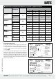
The heating tape is attached to the work-piece by means of
temperature resistant adhesive tape with a maximum distance of
200 mm. Use only plasticiser-free adhesive tapes (no PVC adhesive
tapes)!
To ensure efficient heat transmission, the heating tape must have even
contact over the entire length of the surface. If necessary, the distances
between fastenings must be reduced.
The tape is laid on the pipelines either parallel to the axis of the pipe or
in spiral form (in accordance with the project engineering instructions).
On plastic pipes, which conduct heat less efficiently than metal pipes
do, aluminium foil or aluminium adhesive tape is put under or over the
heating tape. This substantially improves the distribution of heat,
prevents a local accumulation of heat and at the same time it partly
compensates for the lower heat dissipation and associated reduction in
the capacity of the heating tape.
Once the heating system with accessories has been mounted, the
insulation resistance between the heating conductor and the metallic
braid must be verified.
The testing voltage should be at least DC 500 V and the insulation
resistance at least 20 MW EN 60079-30-2 Section 8.3.4)
Mounting, commissioning and operation of self-limiting
parallel heating tape MSB type 07-5804-2**X and type
07-5804-2**Y is not allowed with crossing or overlapping.
Choice of a safety temperature limiter shall comply with
EN 60079-30-1.
Commissioning
The equipment may only be operated if it is clean, in the range of the
operation limits and free of any damage. Electrical systems must be
examined by an electrician before commissioning and afterwards at
certain intervals of time.
þ After mounting and before cut-in the self-limiting heating tape HSB
type 07-5803-***A or BARTEC self-limiting heating tapes MSB type
07-5804-2**X and 07-5804-2**Y must be checked for the electrical
resistance between the active bus wires and the braid or
other equivalent electrically conductive material (refer to IEC/
EN 60079-30-2 clause 8.3.4). It must be at least 20 MW for a
minimum supply voltage of DC 500 V. The use of maximum test voltage
of DC 2500 V is recommended.
þ Refer to IEC EN 60079-30-1 clause 4.3.and 4.4 pre-installation
testing shall include:
þ Individual controls shall be tested to ensure correct calibration
including, but not limited to set points, operating temperature
range and span.
þ Vendor fabricated and assembled control panels shall include
documentation certifying that all wiring, layout and functions are
correct and have been tested. Upon receipt of the control panels
at the work site, a general inspection shall be made to confirm
also that no damage has occurred in transit.