
Technical data

TECHNICAL DATA
The Viking Corporation, 210 N Industrial Park Drive, Hastings MI 49058
Telephone: 269-945-9501 Technical Services 877-384-5464 Fax: 269-818-1680 Email: techsvcs@vikingcorp.com
PREACTION SPRINKLER
SYSTEM
Page 8
February, 2010
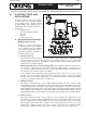
II. SYSTEM TYPES AND
APPLICATIONS
Preaction systems are used in areas where
a common wet pipe or dry pipe sprinkler
system would present a greater potential
of facility damage in the unlikely event of
unintentional water discharge. Examples of
this include:
Computer rooms
Telecommunications facilities
Museums
Libraries
Coolers and freezers
A. Single-Interlocked Preaction
System (Figures 8a-10c)
This type of system is used where it
is desirable to have water available
at the sprinkler when the sprinkler
fuses. Viking single interlock systems
may have a pneumatic, hydraulic, or
electric detection system:
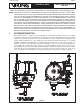
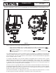
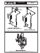
1. Pneumatic Release
A pneumatically actuated system uses a pneumatic actuator subjected to a minimum 30 PSI
(2 bar) air pressure for system water pressures of 175 PSI (12 bar) or less. For system water
pressures above 175 PSI, up to a maximum of 250 PSI (17 bar), 50 PSI (3.4 bar) air pressure is
required for the pneumatic actuator.
When Using a Model E or F Series Deluge Valve: The pneumatic actuator is installed in the
1/2” release line above the pressure operated relief valve (PORV) and the emergency release.
This is done to establish water pressure in the deluge valve prime chamber from air pressure in
the detection system. Refer to Figures 8a and 8b.
In fire conditions, when a heat activated releasing device opens to cause a loss of air pressure in
the release line, the pneumatic actuator opens to vent the pressure in the deluge valve priming
chamber and release the water faster than it can be replaced through the restricted priming line
connection, opening the deluge valve (see Figure 8c).
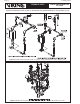
2. Hydraulic Release
This requires a hydraulic release system equipped with thermostatic (rate-of-rise) releases, and/or
fixed-temperature releases, and/or pilot heads. The system piping remains empty until the deluge valve
is activated by operation of the release system. When a releasing device operates, pressure in the
priming chamber of the deluge valve is relieved faster than it can be replenished through the restricted
orifice. Supply pressure overcomes the deluge valve clapper differential, forcing the clapper off its seat,
allowing water to flow to the system outlets and sound the water flow alarm. (Refer to Figures 9a-9b).
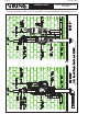
3. Electric Release
Electrically controlled preaction systems require an eletric solenoid valve controlled by an ap-
proved release control panel with compatible detection system. In the SET condition, water supply
pressure is trapped in the priming chamber by check valve and normally closed solenoid valve.
Refer to Figures 10a and 10b. In fire conditions, when the detection system operates, the system
control panel energizes solenoid valve open. Pressure is released from the priming chamber
faster than it is supplied through restricted orifice and the deluge valve opens (Figure 10c).
•
•
•
•
•
Figure 7