
Technical data


TECHNICAL DATA
The Viking Corporation, 210 N Industrial Park Drive, Hastings MI 49058
Telephone: 269-945-9501 Technical Services 877-384-5464 Fax: 269-818-1680 Email: techsvcs@vikingcorp.com
PREACTION SPRINKLER
SYSTEM
Page 60
February, 2010
e. Close the water supply control valve.
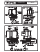
9. To remove / replace the prime coupling (Figures 46-47):
a. Remove the 1/4” socket set screw and nylon ball (for the Model G-4000P Valve only).
b. Open the 1/2” union on the prime line.
c. Using a wrench on the flats of the coupling, remove the coupling from the valve body.
d. Inspect the coupling and 2 o-rings. Replace if necessary.
10. To remove / replace the prime chamber assembly (Figure 48):
a. The prime chamber assembly is now held in place by two flanges on the outside diameter of the
assembly. Slide the prime chamber assembly toward the prime line and remove from the body.
b. Inspect and replace if necessary.
c. Inspect the seat. The seat should be clean and free of foreign material. If the seat is damaged,
the Model G Series Valve must be replaced.
11. To re-assemble the valve:
a. Place the prime chamber assembly in the valve body. Make sure the two flanges are posi-
tioned in the groove.
b. Thread the prime coupling into the valve body. Make sure the end of the prime coupling is
inserted into the prime chamber assembly.
c. Replace the nylon ball and socket set screw (Model G-4000P Valve only).
d. Tighten the 1/4” socket set screw (Model G-4000P Valve only).
e. Lay the check diaphragm into the valve body.
f. Position the cover on the valve body, and install and tighten the cover screws.
g. Re-install any trim that was removed.
h. Place the valve in service by following the steps below.
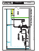
12. Set the Model G Series Valve:
a. Open the flow test valve (Figure 49).
b. Establish air pressure on the system (Figure 50).
c. When air pressure has been established, open the priming valve. Prime water pressure will enter
and expand the valve’s internal diaphragm assembly onto the valve seat, effectively closing the
valve (Figure 51). Verify prime pressure has been established on the prime pressure gauge.
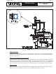
d. Verify that no water flows from the drip check when the plunger is pushed (Figure 52).
e. When the priming pressure has been verified as being established, slowly open the water
supply control valve (Figure 53).
f. When flow is developed from the flow test valve, CLOSE the flow test valve (Figure 54).
g. Fully open the water supply main control valve.
h. Secure all valves in their normal operating position.
i. Notify Authorities Having Jurisdiction and those in the affected area that the system is in service.
j. The system is now fully operational.
VI. REMOVING THE SYSTEM FROM SERVICE
WARNING: The system should be placed out of service only for repairs. The work must be completed in
a manner to minimize the time that the system must be out of service. All hazardous activities in the ef-
fected area shall be terminated until the system is placed back in service. Any system impairment shall be
coordinated with the owner, local authority having jurisdiction, and other related parties. Place a roving fire
patrol in the area covered by the system until the system is back in service.
Prior to turning off any valves or activating any alarms, notify local security guards and/or central alarm
station (if used) so that a false alarm will not be signalled and result in a local fire department response.
1. Close the water supply control valve.
2. Close the priming valve.