
Technical data


Page 59
TECHNICAL DATA
The Viking Corporation, 210 N Industrial Park Drive, Hastings MI 49058
Telephone: 269-945-9501 Technical Services: 877-384-5464 Fax: 269-818-1680 Email: techsvcs@vikingcorp.com
February, 2010
PREACTION SPRINKLER
SYSTEM
NOTE: THE SPACER’S OUTSIDE DIAMETER IS TAPERED. THE DIAMETER OF THE BOTTOM
IS GREATER THAN THE DIAMETER OF THE TOP.
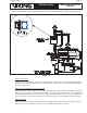
b. Align bolt holes and tighten screws.
4. Place the cover, with cap screws inserted in the holes, upside down on a work bench.
5. With the top side of the spacer and upper diaphragm toward the cover, place the clapper assem-
bly and spacer, described in Step 3, over the threaded ends of cap screws.
a. Upper diaphragm must be flat between the cover and spacer.
b. The piston should protrude from the spacer, and the clapper assembly should be visible (fac-
ing up).
6. Gently roll the lower diaphragm over the protruding piston and position the bolt holes of the lower
diaphragm over the threaded ends of the cap screws.
7. Taking care not to cut the diaphragm, tuck the lower diaphragm between the spacer and piston
around the entire circumference of the piston while gently pushing the piston into the spacer.
8. Carefully position the cover with cap screws and piston assembly on the valve body.
9. Remove the cover with cap screws and verify that upper diaphragm is properly tucked between
the spacer and piston around the entire circumference of the piston.
10. Install cover and cap screws.
a. Lower diaphragm must be flat between the spacer and body.
b. Cross tighten cap screws uniformly. Do not over-tighten.
11. The valve must be operated after reassembly to verify all parts function properly.
Maintenance for the Model G Series Valve (Refer to Figures 37-48.)
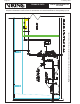
1. Close the water supply main control valve (Figure 37), placing the system out of service.
2. Open the flow test valve located in the base of the Model G Series Valve (Figure 38).
3. Close the air (or nitrogen) supply to the preaction system piping and pilot line (Figure 39).
4. Close the priming valve (Figure 40).
5. Relieve all pressure from the preaction system piping and pilot line. If the system has operated
(Figure 41), open the main drain valve to allow the system to drain completely.
6. To remove the cover from the body (Figures 42a-42b):
a. Remove the coupling from the top of the Model G Series Valve.
b. Remove the section of pipe directly above the deluge valve, if provided.
c. Remove the air supply line.
d. Remove the coupling or open the union below the main drain, if provided.
e. Remove the cover screws.
f. The cover and trim that is still connected may now be removed from the body. (It may be neces-
sary to pry the valve open as the diaphragm may bond itself to the cover and body over time.)
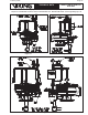
7. To remove / replace the check diaghphragm (Figure 43):
a. The check diaghphragm may be lifted from the valve body.
b. If nescessary, replace the check diaphragm.
8. To inspect the prime chamber and coupling for leaks (Figures 44-45):
Note: If desired, it is possible to set the Model G Series Valve and inspect for leaks with the cover
removed.
a. Remove the pneumatic actuator (for pneumatic release systems) and temporarily plug the 1/2”
prime line. (Plug the outlet of the NO solenoid valve on Surefire
®
Preaction Systems.
b. Slowly open the prime valve.
c. With prime water established, partially open the main water supply control valve.
d. Visually inspect the inside of the deluge valve for leaks.