
Technical data


Page 55
TECHNICAL DATA
The Viking Corporation, 210 N Industrial Park Drive, Hastings MI 49058
Telephone: 269-945-9501 Technical Services: 877-384-5464 Fax: 269-818-1680 Email: techsvcs@vikingcorp.com
February, 2010
PREACTION SPRINKLER
SYSTEM
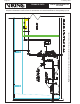
Auxiliary Drains
Section 8.16.2.5.3 of NFPA 13† requires auxiliary drains where a change in piping direction prevents drain-
age of system piping through the main drain valve. Where the capacity of trapped sections of pipe is less
than 5 gal (18.9 L), the drain shall consist of a valve at least 1/2” (15 mm) and a plug or nipple and cap.
Where the capacity of isolated trapped sections of system piping is more than 5 gal (18.9 L), the auxiliary
drain shall consist of two 1” (25 mm) valves and one 2” x 12” (50 mm x 305 mm) condensate nipple or
equivalent, accessibly located in accordance with Figure 8.16.2.5.3.4 of NFPA 13†. Note that listed equiva-
lent products are now available.
Tie-in drains are not required on preaction systems protecting non-freezing environments. Adjacent trapped
branch lines must be provided with tie-in drains. It is recommended to limited the number of branch lines
tied together; the tie-in drains are restricted to a maximum of 1” (25 mm). Auxiliary drains located in areas
subject to freezing shall be readily accessible.
Systems with low point drains shall have a sign at the preaction valve indicating the number of low point
drains and the location of each individual drain.
NOTE: Auxiliary drains are not for pipe drops supplying dry pendent sprinklers installed in accordance with
section 7.2.2 of NFPA 13†.
†NFPA 13 or NFPA 72-2007 edition.
IV. PLACING THE SYSTEM IN SERVICE
(Refer to technical data.)
V. PREACTION SYSTEM INSPECTIONS, TESTS, AND MAINTENANCE
NOTICE: THE OWNER IS RESPONSIBLE FOR MAINTAINING THE FIRE-PROTECTION SYSTEM
AND DEVICES IN PROPER OPERATING CONDITION. THE DELUGE VALVE MUST BE KEPT FROM
FREEZING CONDITIONS AND PHYSICAL DAMAGE THAT COULD IMPAIR ITS OPERATION.
WARNING: ANY SYSTEM MAINTENANCE THAT INVOLVES PLACING A CONTROL VALVE OR DETEC-
TION SYSTEM OUT OF SERVICE MAY ELIMINATE THE FIRE-PROTECTION CAPABILITIES OF THAT SYS-
TEM. PRIOR TO PROCEEDING, NOTIFY ALL AUTHORITIES HAVING JURISDICTION. CONSIDERATION
SHOULD BE GIVEN TO EMPLOYMENT OF A FIRE PATROL IN THE AFFECTED AREAS.
It is imperative that the system be inspected and tested on a regular basis in accordance with NFPA 25.
During all inspections, testing, and maintenance activities the valve, trim, piping, alarm devices, and con-
nected equipment must be visually inspected for foreign matter, physical damage, freezing, corrosion, or
other conditions that may inhibit the proper operation of the system.
The following recommendations are minimum requirements. The frequency of the inspections may vary
due to contaminated or corrosive water supplies and corrosive atmospheres. In addition, the alarm de-
vices, detection systems, or other connected equipment may require more frequent inspections. Refer to
the system description, sections in this manual specifically for each component of the system and type of
release system, applicable codes, and the authority having jurisdiction for minimum requirements. Prior to
testing the equipment, notify appropriate personnel.
Weekly visual inspection of the Viking deluge valve is recommended.
1. Verify that the main water supply control valve is open and that all other valves are in their normal
operating position and appropriately secured. For normal operating position, refer to trim charts and
system data for the system used.
2. Check for signs of mechanical damage, leakage, and/or corrosive activity. If detected, perform main-
tenance as required. If necessary, replace the device.
3. Verify that the valve and trim are adequately heated and protected from freezing and physical damage.