
Technical data
TECHNICAL DATA
The Viking Corporation, 210 N Industrial Park Drive, Hastings MI 49058
Telephone: 269-945-9501 Technical Services 877-384-5464 Fax: 269-818-1680 Email: techsvcs@vikingcorp.com
PREACTION SPRINKLER
SYSTEM
Page 50
February, 2010
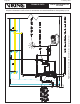
Figure 31
Pressure to be Maintained in a Pneumatic Release System: For recommended pneumatic (air or nitrogen)
pressures to be maintained in pneumatic release systems, refer to current Viking technical data for the system
used. For additional information concerning pneumatic release system equipment, devices, and installation
instructions, refer to the Viking Engineering and Design Data book section describing Pneumatic Supplies.
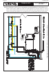
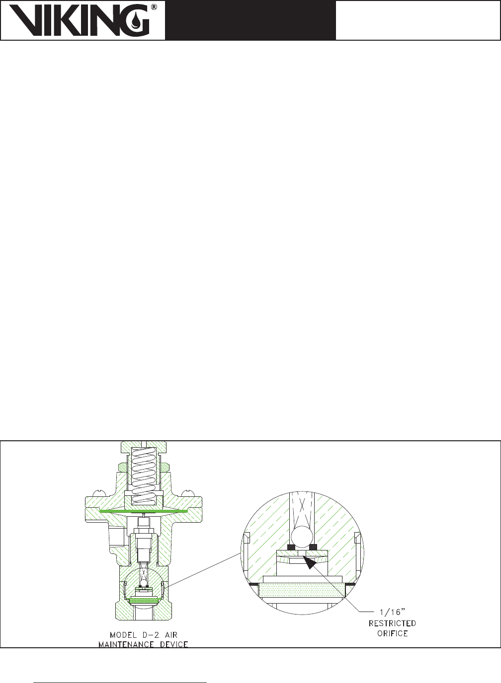
Release Line Restriction: All pneumatic-release systems must be equipped with a restricted orifice in the
air or nitrogen supply to ensure that the automatic air supply cannot replace pneumatic pressure as fast
as it escapes when a releasing device operates.
This restriction is already incorporated in the Viking air maintenance device and release line air supply
assembly. The air maintenance device contains a 1/16 inch (.16 mm) orifice (Figure 31), which restricts
the flow of air into the system so that when a sprinkler opens, air pressure will not enter the system faster
than it will discharge through a sprinkler. The bypass valve is kept closed and opened only to speed up the
filling of the system piping to the required pressure in the required time.
Reducing Trip Time: If the system trip time is excessive, it can be substantially reduced by one or more of
the following:
1. Add a check valve (Circle Seal or equivalent) in branch portions of the release-line system. (Install
so flow is toward releasing device).
2. Install an optional accelerator on the pneumatic release system to provide earlier alarms and/or allow the
system to trip faster. An accelerator may be necessary to meet system discharge time requirements.
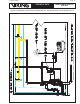
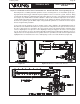
Release Line Dehydrator: Due to problems that accumulated condensation can cause, especially on
freezer systems, all pneumatic release systems must be provided with a properly sized and maintained air
dehydrator installed on the air supply (Figure 32). It is important that the color of the desiccant be checked
at regular intervals to ensure its drying capability.
Pneumatic Supply: Refer to Viking technical data, system data, and associated schematic drawings for
the preaction system used. Also, refer to the Viking Engineering and Design Data book section describing
“Pneumatic Supplies” for additional information on pneumatic (air or nitrogen) equipment, devices, and
installation requirements.
Electric Release System Requirements
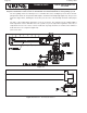
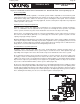
Viking preaction systems can be activated electrically through the use of a solenoid valve (Figures 32 and
33). The solenoid reacts to device actuation by opening, relieving pressure from the priming chamber of
the deluge valve (Figure 34). Note the electrical characteristics of the solenoid valve, as it must be compat-
ible with the system control panel and other electrical components. Observe all manufacturer’s technical
instructions.