
Technical data


Page 5
TECHNICAL DATA
The Viking Corporation, 210 N Industrial Park Drive, Hastings MI 49058
Telephone: 269-945-9501 Technical Services: 877-384-5464 Fax: 269-818-1680 Email: techsvcs@vikingcorp.com
February, 2010
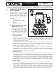
PREACTION SPRINKLER
SYSTEM
NFPA 13 defines three basic types of preaction systems:
Single Interlocked: Admits water to sprinkler piping upon operation of detection devices only.
Double Interlocked: Admits water to sprinkler piping upon operation of both the detection devices
and automatic sprinklers.
Non-Interlocked: Admits water to sprinkler piping upon either operation of detection devices or
automatic sprinklers.
The supplemental detection system is commonly electric or pneumatic or a combination of both. Detection
systems used with electric release systems are commonly actuated by manual pull stations, fixed-tempera-
ture heat detectors, rate-of-rise heat detectors, smoke detectors or other means determined as appropriate
by the specifying engineers or AHJ.
In accordance with NFPA 13, the preaction sprinkler system piping and fire detection devices shall be
automatically supervised where there are more than 20 sprinklers on the systems. This is accomplished
with air or nitrogen gas under pressure within the sprinkler piping. If the integrity of the sprinkler piping
is comprimised, the pressure will be reduced activating a supervisory pressure switch that transmits the
signal to the release control panel and/or fire alarm panel.
Preaction systems are typically utilized where it is desirable to delay the introduction of water into the sys-
tem piping until appropriate signals are received from the detection system and/or the supervised piping.
Exactly which signals and how many signals have to be received before the valve opens is a function of
the type of preaction system and associated detection.
This technical manual will cover Viking preaction systems, trim components and their functions, as well as
describe the proper operation, maintenance, and repair of valves and system devices.
•
•
•
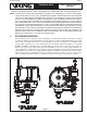
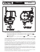
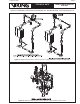
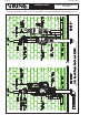
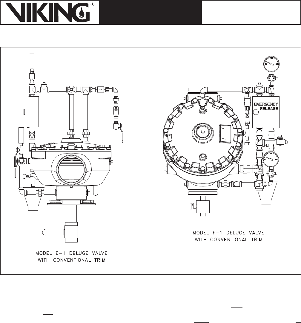
Figure 2