
Technical data
TECHNICAL DATA
The Viking Corporation, 210 N Industrial Park Drive, Hastings MI 49058
Telephone: 269-945-9501 Technical Services 877-384-5464 Fax: 269-818-1680 Email: techsvcs@vikingcorp.com
PREACTION SPRINKLER
SYSTEM
Page 48
February, 2010
Device Compatibility
All components of pneumatic, hydraulic, or electrical systems shall be compatible to ensure that all system
components function as an integrated unit. For example, in electrical systems, the solenoid valve must be
listed with the deluge valve, and the fire detection system, including the control panel. Correct coordina-
tion of the detection devices, the releasing equipment, and the control panel is imperative for prompt and
reliable operation of the system.
Hydraulic Release System Requirements
Hydraulic release systems may utilize rate-of-temperature rise, fixed-temperature, manual releasing de-
vices, or combinations thereof. Hydraulic release systems are normally the least expensive of possible
release systems; however, they must not be installed in areas that are not subject to freezing.
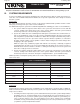
Release Lines: Use galvanized steel pipe or corrosion-resistant tubing, such as copper or brass for release
lines. Do not exceed 1,000 ft. (304.8 m) of ½” (15 mm) pipe in a release-line system. In systems over this
capacity, larger pipe sizing is required.
Maximum Allowable Height Of Release Line Above The Deluge Valve: Under certain conditions, the deluge
valve may be subject to water columning. To prevent this, hydraulic release system piping must not exceed
the maximum elevation allowed for hydraulic release piping above the deluge valve as indicated in the
listing. Refer to current technical data for the Viking deluge valve used.
Pneumatic Release System Requirements
Pneumatic release systems may utilize rate-of-rise, fixed-temperature, manual releasing devices, or
combinations thereof. Pneumatic release systems may be used in most areas. Valve trip-time may vary
depending on the length of the release line and the air pressure maintained on the release system.
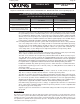
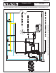
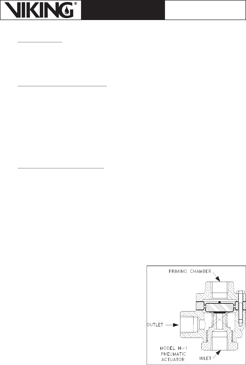
Air is commonly used in the release line where freezing is a concern. However, air systems require a dry
air supply, a means of transitioning from air to water in the release line, and a release line maximum of
1,000 ft. The device used to accomplish the transition is Viking’s Model H-1 Pneumatic Actuator (Figure
26). Its inlet is subject to system water pressure (Figure 27). Its priming chamber is subject to release line
air pressure of 30 PSI minimum and its outlet is open to drain (Figure 28).
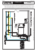
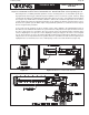
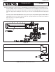
Air pressure on the priming chamber of the actuator forces the diaphragm and piston assembly to seal the
inlet from the outlet (Figure 29). With its differential design, the relatively low pressure in the priming cham-
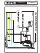
ber will control a higher water inlet pressure. When a pilot line release opens and relieves air pressure in the
actuator priming chamber, the inlet pressure and the spring force the diaphragm and the piston assembly to
move, allowing the inlet water pressure to be relieved through the outlet (Figure 30).
Figure 26