
Technical data
TECHNICAL DATA
The Viking Corporation, 210 N Industrial Park Drive, Hastings MI 49058
Telephone: 269-945-9501 Technical Services 877-384-5464 Fax: 269-818-1680 Email: techsvcs@vikingcorp.com
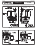
PREACTION SPRINKLER
SYSTEM
Page 42
February, 2010
Set release system air pressure supervisory switch to activate at 25 PSI (1.7 bar) on pressure drop
for system water pressures of 175 PSI (12 bar) or less. For system water pressures above 175 PSI,
up to a maximum of 250 PSI (17 bar), set the air pressure supervisory switch to activate at 45 PSI
(2.4 bar) on pressure drop. Air pressure supervisory switch should be wired to activate an alarm to
signal a low air pressure condition. Activation of an alarm to signal a high pressure condition may be
required. Refer to applicable installation standards and the Authority Having Jurisdiction.
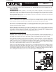
2A. For Viking double interlock preaction systems with electric/pneu-lectric release using a Model E
or F series deluge valve: Refer to the settings in Table 2. Recommended pneumatic supervisory
pressure in the closed sprinkler piping is 30 PSI (2.1 bar). The air supervisory switch should be
equipped with two sets of independently adjustable contacts. On systems with a Model E or F
series deluge valve, use the Viking Pressure Supervisory Switch as air supervisory switch.
For 30 PSI (2.1 bar) supervisory pressure:
Adjust one set of contacts of air supervisory switch to activate at 25 PSI (1.7 bar) on pressure drop.
These contacts should be wired to activate a “Low-Air” supervisory alarm.
The other set of contacts in the air supervisory switch should activate at 20 PSI (1.4 bar) on pres-
sure drop. Wire these contacts to activate the remaining initiating circuit of the system control panel
configured for “cross-zoned” operation. For the VFR400 Release Control Panel, refer to the appropriate
wiring diagram packed with the panel. Activation of an alarm to signal a high-pressure condition may
be required. Refer to applicable installation standards and the Authority Having Jurisdiction.
Installation Standards may allow supervisory pressures lower than those recommended above.
For pneumatic supervisory pressure of 10 PSI (.7 bar), use Viking Alarm Pressure Switch as air
supervisory switch.
For 10 PSI (.7 bar) Supervisory Pressure:
Adjust one set of contacts of air supervisory switch to activate at 7.5 PSI (.52 bar) on pressure
drop. These contacts should be wired to activate a “Low-Air” supervisory alarm.
The other set of contacts in air supervisory switch should activate at 5 PSI (3.4 bar) on pressure drop.
Wire these contacts to activate the remaining initiating circuit of the system control panel configured
for “cross-zoned” operation. For the VFR400 Release Control Panel, refer to the appropriate wiring
diagram packed with the panel. Activation of an alarm to signal a high-pressure condition may be
required. Refer to applicable installation standards and the Authority Having Jurisdiction.
Note: When using supervisory pressures, settings, or equipment other than those recommended
above, verify that air regulation equipment and air supervisory switches used are compatible with
the supervisory pressure setting used.
Supervisory pressures other than the recommended settings noted above may affect operation of
the system.
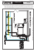
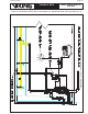
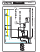
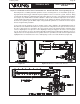
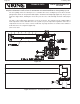
Release Devices
The release system shall serve all areas that the preaction system protects to ensure that in the event of
a fire, the release system will activate and provide water to the system and the affected area. There are
a number of release system devices that can be used in the detection system. The simplest of these is to
use sprinklers in a pilot line under system water pressure. The pilot line is piped to the area protected with
connections to the emergency release.
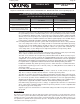
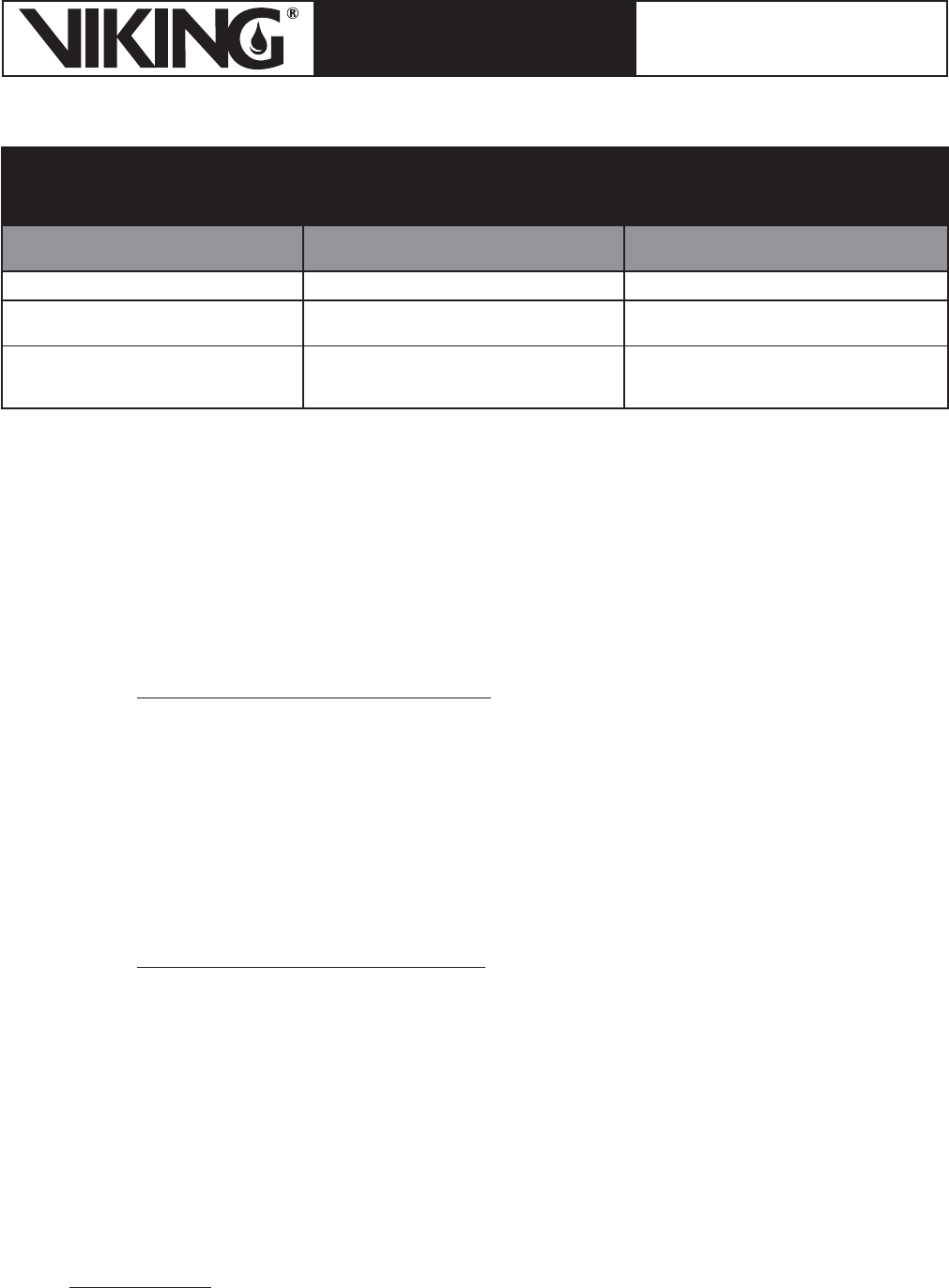
TABLE 2: RECOMMENDED PNEUMATIC SUPERVISORY PRESSURES AND SETTINGS
FOR VIKING DOUBLE INTERLOCK PREACTION SYSTEMS WITH ELECTRIC/PNEU-LECTRIC RELEASE
(FOR SYSTEMS USING A MODEL E OR F SERIES DELUGE VALVE)
Device
For Supervisory Pressure of 30 PSI (2.1 bar)
Set to Maintain
For Supervisory Pressure of 10 PSI (.7 bar)
Set to Maintain
Air Maintenance Device 30 PSI (2.1 bar) 10 PSI (.7 bar)
Low-Air Alarm Contact Setting on Release
System Pressure Supervisory Switch
25 PSI (1.7 bar) On Pressure Drop 7.5 PSI (.52 bar) On Pressure Drop
Setting for Contacts on Release System
Pressure Supervisory Switch to activate
Release Control Panel Initiating Circuit
20 PSI (1.4 bar) on Pressure Drop 5 PSI (.34 bar) on Pressure Drop