
Technical data


TECHNICAL DATA
The Viking Corporation, 210 N Industrial Park Drive, Hastings MI 49058
Telephone: 269-945-9501 Technical Services 877-384-5464 Fax: 269-818-1680 Email: techsvcs@vikingcorp.com
PREACTION SPRINKLER
SYSTEM
Page 36
February, 2010
Trimpac
®
can be utilized for systems regardless of valve size. A valve drain package is required for the del-
uge/flow control valve and is ordered based on valve size.
NOTE: The Trimpac
®
trim assembly must be installed to facilitate drainage, must be installed an area not
subject to freezing, and must be installed above the elevation of the drip check valve. Refer to the technical
data pages.
Trimpac
®
Air Line Trim
Trimpac
®
air line trim is for use with Trimpac
®
single interlock or double interlock preaction systems including
Surefire
®
(see Figure 17 for example). The air line connects to the pneumatic sensing line of the Trimpac
®
cabinet and includes approximately 10 ft of copper tubing, air gauge, an air maintenance loop (when used with
a tank mounted compressor), pressure switch, check valve, and fittings. Note that the Trimpac
®
air line trim is
ordered separately from the Trimac
®
. Refer to technical data pages for additional information.
E. TRIMPAC
®
SUREFIRE
®
Viking’s Trimpac
®
Surefire
®
is unique system that provides failsafe operation upon loss of the primary
and secondary power supplies. The Surefire
®
system is a factory assembled trim package for use
with a deluge valve, with standard trim contained in a Trimpac
®
cabinet as described on page 35.
Trimpac
®
eliminates the field assembly of the deluge valve trim and release module piping. Trimpac
®
Surfire
®
Single Interlock or Double Interlock Preaction Systems are designed with an electric release
system.
The system piping is normally dry and pnuematically pressurized to supervise the integrity of the pip-
ing, fitting and sprinklers.
1. Trimpac
®
Surefi re
®
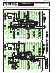
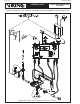
Single Interlock Preaction System (Figure 18a)
System water supply pressure enters the priming chamber of the deluge valve through the 1/2”
(13 mm) priming line, which includes a normally open priming valve, strainer, restricted orifice,
and check valve. In the SET condition, water supply pressure is trapped in the priming chamber
by check valve, normally closed emergency release, pressure operated relief valve, pneumatic
actuator, and normally closed release solenoid valve. Water supply pressure in the priming cham-
ber holds the clapper of the deluge valve on the seat due to the differential design of the valve
pressure. The clapper separates the inlet chamber from the outlet chamber, keeping the outlet
chamber and system piping dry.
In fire conditions, when the detection system operates, the VFR400 Control Panel activates the
system alarm and energizes normally closed release solenoid valve open. Pressure is released
from the priming chamber faster than it is supplied through restricted orifice. The deluge valve
clapper opens to allow water to flow into the system piping and to alarm devices. Water entering
the system piping increases pressure on the PORV, which vents the water supply to the prime
chamber. Water will flow from any open sprinklers or nozzles.
2. Trimpac
®
Surefi re
®
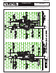
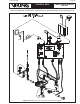
Double Interlock Preaction System (Figure 18b)
System water supply pressure enters the priming chamber of the deluge valve through the 1/4”
(8 mm) hose and 1/2” priming line which includes a normally open priming valve, strainer, re-
stricted orifice and check valve. In the SET condition, water supply pressure is trapped in the prim-
ing chamber by check valve, normally closed emergency release, pneumatic actuator, pressure
operated relief valve (PORV) and normally closed release solenoid valve. Water supply pressure
in the priming chamber holds the clapper of the deluge valve on the seat due to the differential
design of the valve pressure. The clapper separates the inlet chamber from the outlet chamber,
keeping the outlet chamber and system piping dry.