
Technical data
TECHNICAL DATA
The Viking Corporation, 210 N Industrial Park Drive, Hastings MI 49058
Telephone: 269-945-9501 Technical Services 877-384-5464 Fax: 269-818-1680 Email: techsvcs@vikingcorp.com
PREACTION SPRINKLER
SYSTEM
Page 18
February, 2010
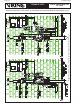
B. Double-Interlocked Preaction System (Figures 11a-13c)
This system is commonly used in freezers where flooding of the pipe can have serious consequences.
The double interlock preaction system utilizes a detector system and pressurized air or nitrogen in
the sprinkler system piping. This system is arranged so that the deluge valve will open only when
both pressure is reduced in the sprinkler piping and the detection system operates. If the detection
system operates due to damage or malfunction, the valve will not open, but an alarm will sound. If the
sprinkler piping is damaged or sprinkler is broken, the valve will not open but a supervisory alarm will
sound. The operation of both a sprinkler and a detector (or release) is required before the valve will
open, allowing water to enter the system piping. Viking strongly suggests that the detection system
not be hung from or attached to the system piping. This is to help prevent accidental damage to both
systems, which would cause the deluge valve to operate and cause unnecessary water damage.
Viking double interlock systems commonly have a pneumatic or electric detection system:
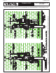
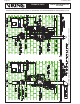
1. Electric/Pneumatic Release
Refer to Figure 11a and 11b. This system uses the same electrical detection system as previously
discussed. The operation of an electric detection system depends on the activation of a detector,
which signals the release control panel to open a solenoid valve and activate an electric alarm.
However, the system will not trip unless a sprinkler fuses, releasing the air pressure on the pneu-
matic actuator, allowing it to open, relieving the release line pressure. When that happens, the
deluge valve opens (Figure 11c).
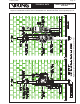
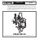
With the Model G Series Valve: With both the pneumatic actuator and solenoid valve open,
prime water is drained from the prime chamber, causing the rolling diaphragm to collapse and the
deluge valve to open, filling the sprinkler piping with water. Water from the intermediate chamber
of the deluge valve pressurizes the sensing end of the PORV, causing the PORV to open, which
continually vents prime water pressure (Figure 11d).
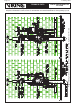
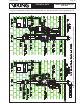
2. Pneumatic/Pneumatic Release
In a pneumatic/pneumatic system, the air pressure is supplied to the release line through two in-
dependently controlled pneumatic actuators. One of these is controlled by air pressure maintained
in the pneumatic release system. The other, by air pressure maintained in the sprinkler system.
(Refer to Figures 12a and 12b.) In fire conditions, the release system operates and loss of pres-
sure in that system causes the first pneumatic actuator to open.
When a sprinkler operates, loss of pressure in the sprinkler piping causes the second pneumatic
actuator to open, releasing water in the deluge valve’s priming chamber (Figure 12c). When water
in the priming chamber is released, the deluge valve opens and fills the sprinkler piping.
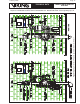
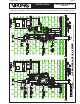
3. Electric/Pneu-Lectric Release
In double interlock electric/pneu-lectric systems, the first signal is the electrical detection system.
The second signal required to trip the deluge valve is provided by an air supervisory switch on
the sprinkler system piping. The air supervisory switch is connected to the Viking VFR-400 Panel,
which is cross zoned with the detection system. (Refer to Figures 13a-13c).
If system piping is damaged, an alarm will sound, but the system will not actuate. Similarly, if the
electric detection system is damaged, the valve will not open.