
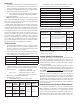
Technical data


6.
Energizing the releasing solenoid valve allows the deluge valve’s
push-rod chamber to be vented to drain through its outlet. Since
the pressure cannot be replenished through the inlet restriction
as rapidly as it is vented though the outlet, the push-rod cham-
ber pressure falls rapidly. When the push-rod chamber pressure
drops below one-third of the supply pressure, the opening force
acting beneath the clapper becomes greater than the push-rod
force acting on the lever. This causes the clapper to open. Refer
to Reliable Bulletins 512 and 513 for further details.
Once the clapper has opened, the lever acts as a latch, prevent-
ing the clapper from returning to the closed position. Water from
the supply flows through the deluge valve into the system piping.
Water also flows through the deluge valve alarm outlet to activate
any water flow alarm devices. Note that the solenoid valve will be
maintained open by the Potter Model PFC-4410-RC Releasing
Control Panel’s latching feature until it is reset for operation.
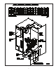
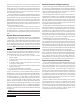
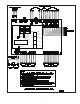
After system shutdown and draining, the Model DDX Deluge
Valve is easily reset without special tools (see Fig.8). Restore de-
tection devices by resetting or replacing any operated device.
Once detection devices are restored, (the Potter Model PFC-
4410-RC Releasing Control Panel reset), and supply pressure is
re-supplied to the push-rod chamber, the deluge valve is reset.
Maintenance
The Reliable Model DDX PrePaK and associated equipment
shall periodically be given a thorough inspection and test. NFPA
25, Inspection, Testing and Maintenance of water Based Fire Pro-
tection Systems, provides minimum maintenance requirements.
Systems should be tested, operated, cleaned and inspected at
least annually, and parts replaced as required. Periodically open
the air/condensate drain valve (refer to Fig. 8) beneath the air tank
to drain any condensate accumulation. Bulletin 512 provides
information for maintaining the Model DDX Deluge Valve. Potter
Manual #5403550 provides information for maintaining the PFC-
4410-RC Releasing Control Panel.
Resetting Single And Double Interlock Systems
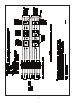
Refer to Fig. 8.
Close the main valve controlling water supply to the deluge
valve and close the ¼” air shutoff valve, valve J.
Close the pushrod chamber supply valve, valve A.
Open the main drain valve, valve B, and drain system.
Open all drain valves and vents at low points throughout
the system, closing them when flow of water has stopped.
Open valve D. Note: The above steps accomplish the
relieving of pressure in the pushrod chamber of the deluge
valve.
Push in the plunger of ball drip valve, valve F, to force the
ball from its seat, and drain any water in the alarm line.
With the Model B Manual Emergency Station, valve D,
open, push in and rotate the deluge valve’s external reset
knob clockwise until you hear a distinct clicking noise, indi-
cating that the clapper has closed. Note: The reset knob
can be rotated only after pressure in the pushrod chamber
is reduced to atmospheric conditions (0 psig).
Inspect and replace any portion of the sprinkler system
subjected to fire conditions.
Verify that the following valves are in their respective posi-
tions:
valve C – open, valve E – closed, valve H – closed,
valve K – open, valve M – closed.
Open valve A and allow water to fill the deluge valve’s push-
rod chamber. Close valve D.
Bleed any air from the actuation piping by energizing the
solenoid valve. This is done by operating a detector or an
electric manual emergency station. While water is flowing
through the solenoid valve, cause it to close by pressing the
system reset button on the Potter PFC-4410-RC Releasing
Control Panel. Note: All detection devices must be reset
before the releasing/control panel can be reset.
Open the ¼” air shutoff valve, valve J, to restore air pres-
sure in the sprinkler system. The rapid air-fill shutoff valve,
valve M, may be opened here to expedite the filling of the
sprinkler system.
Open slightly the main valve controlling water supply to
the Model DDX Deluge Valve, closing drain valve B when
water flows. Observe if water leaks through the ball drip
valve, valve F, into the drip cup, G. If no leak occurs, the
deluge valve’s clapper is sealed. Open slowly, and verify
that the main valve controlling water supply is fully opened
and properly monitored.
Verify that valve A is open.
Secure the handle of the Model B Manual Emergency Sta-
tion, valve D, in the OFF position with a nylon tie (supplied
with the assembly).
Press the system reset button on the Potter PFC-4410-RC
Panel to place the system in the ready condition. Note: All
detection devices must be reset before the panel can be
reset.
1.
2.
3.
4.
5.
6.
7.
8.
9.
10.
11.
12.
13.
14.
15.