
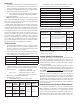
Technical data


5.
pressor. The air compressor is connected to an 2 gallon (9.1 liter)
ASME rated storage tank. This tank functions as a reservoir, pro-
viding make-up air to compensate for small, intermittent leaks in
the sprinkler system. It should be noted that significant leaks may
overburden this storage tank, thereby causing the air compressor
to continuously cycle on and off.
The Pressure Maintenance Device supplied with the system (re-
fer to Fig. 8), is factory set to maintain system pneumatic pressure
at approximately 10 psi (0,7 bar). Readjusting system pressure to
approximately 10 psi (0,7 bar), if necessary, is accomplished by
first loosening the locknut on the air pressure regulator and turn-
ing the adjustment screw (refer to Fig. 8). The system air pressure
gauge that is included in the trim may be used to verify the cor-
rect level of pneumatic pressure.
The system air pressure switch (refer to Fig. 8) is factory set
to operate between 8 psi and 4 psi (0,6 bar and 0,3 bar) with
decreasing pressure. Adjustment, if required, should be made
according to System Sensor Bulletin A05-0176 included with the
switch.
System Electrical Requirements
All releasing, alarm, and detection devices in the Reliable Mod-
el DDX 2” (50 mm), 2½” (65 mm) and 3” (80 mm) PrePaKs are
supervised by a Potter Model PFC-4410-RC Releasing Control
Panel. To utilize one of the doors of the steel enclosure as a mount
for the releasing control panel, all of the terminals are translated
to two, water-tight terminal boxes mounted on the interior of the
enclosure. Note: the EOL (End of Line) resistors have also been
relocated. It is from these terminal boxes that all field wiring is con-
nected. There is one terminal box that contains the 24 VDC con-
nections and one that contains the 120 / 220 VAC connections.
The Reliable Model DDX PrePaK is delivered with five factory-in-
stalled electrical devices. They consist of the following:
A system air pressure switch, which is used to monitor
sprinkler piping.
An alarm pressure switch, which indicates an actuation of
the deluge valve.
A normally-closed, releasing solenoid valve, which is used
to actuate the deluge valve.
A HP ( HP for 3” size) tank-mounted air compressor with 2
gallon (9.1 liter) tank.
A supervised butterfly water control valve.
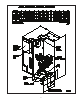
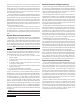
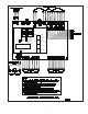
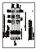
The factory electrical connections of these devices are illustrated
in Fig. 4. For information on how to install fire detection devices to
initiating Zones 1 and 2 of the Potter Model PFC-4410-RC Releas-
ing Control Panel, refer to Fig. 5 or Fig. 6. For information on how
to install output devices, i.e., alarm bells or trouble annunciators,
to the Potter Model PFC-4410-RC Releasing Control Panel, refer
to Fig. 7. The power supply, standby emergency power supply,
battery charger and rectifier circuitry are all contained within the
PFC-4410-RC panel. Batteries that provide 90 hours of standby
power are provided with the panel. For additional information
and detailed wiring diagrams, refer to Potter Manual #5403550,
Installation, Operation and Instruction of PFC-4410-RC Releasing
Control Panel.
Caution: Repairs or disassembly of the solenoid valve should
only be done by a trained technician. An improperly repaired or
partially assembled solenoid valve could result in failure of the
valve to operate.
1.
2.
3.
4.
5.
System Operation (Single Interlock)
To fully activate (water flow) the Reliable Model DDX 2” (50 mm),
2½” (65 mm) or 3” (80 mm) PrePaK in a single interlock applica-
tion, a fire detection device (smoke, heat, etc.) (two detectors with
cross-zoned detection) must activate. Subsequently, a sprinkler
head must open to discharge water on the fire.
When the single interlock preaction system is set for service, the
supply pressure acts both on the underside of the deluge valve’s
clapper and on the valve’s push rod by means of the pressurized
push rod chamber. The pressure force acting on the push rod,
when utilized with the mechanical advantage of the deluge valve’s
lever, is more than sufficient to hold the clapper in the closed posi-
tion against the water supply pressure.
Energizing the releasing solenoid valve allows the deluge valve’s
push-rod chamber to be vented to drain through its outlet. Since
the pressure cannot be replenished through the inlet restriction
as rapidly as it is vented though the outlet, the push-rod cham-
ber pressure falls rapidly. When the push-rod chamber pressure
drops below one-third of the supply pressure, the opening force
acting beneath the clapper becomes greater than the push-rod
force acting on the lever. This causes the clapper to open. Refer
to Reliable Bulletins 512 and 513 for further details.
Once the clapper has opened, the lever acts as a latch, prevent-
ing the clapper from returning to the closed position. Water from
the supply flows through the deluge valve into the system piping.
Water also flows through the deluge valve alarm outlet to activate
any water flow alarm devices. Note that the solenoid valve will be
maintained open by the Potter Model PFC-4410-RC Releasing
Control Panel’s latching feature until it is reset for operation.
After system shutdown and draining, the Model DDX Deluge
Valve is easily reset without special tools (see Fig.8). Restore de-
tection devices by resetting or replacing any operated device.
Once detection devices are restored, (the Potter Model PFC-
4410-RC Releasing Control Panel reset), and supply pressure is
re-supplied to the push-rod chamber, the deluge valve is reset.
System Operation (Double Interlock)
To fully activate (water flow) the Reliable Model DDX 2” (50 mm),
2½” (65 mm) or 3” (80 mm) PrePaK in a double interlock appli-
cation, two independent events must coexist. An electrical fire
detection device (smoke, heat, etc.) and the system air pressure
switch must be activated. This pressure switch is activated by a
reduction of the system’s pneumatic pressure (as a result of sprin-
kler operation). Both of these events will cause the control panel
to energize the solenoid valve, thereby releasing water through
the deluge valve and into the sprinkler system. The initiation of
either one of these events will only cause an alarm to annunciate,
and will not fill the sprinkler system.
When the double interlock preaction system is set for service,
the supply pressure acts both on the underside of the deluge
valve’s clapper and on the valve’s push rod by means of the pres-
surized push rod chamber. The pressure force acting on the push
rod, when utilized with the mechanical advantage of the deluge
valve’s lever, is more than sufficient to hold the clapper in the
closed position against the water supply pressure.