
Technical data


4.
Approvals
Underwriters Laboratories, Inc. Listed and Certified for Can-
ada* (cULus) as an assembled unit in the “Special System
Water Control Valves Assembled Units” category, (VKYL).
Factory Mutual (FM) Approved, as PrePak Single Interlock
and Double Interlock Preaction Systems.
Electrical devices and control panel must be specified to
meet Canadian requirements. This option is available.
NYC MEA 258-93-E
Note: Although PrePak units are UL Listed, custom built units
are sometimes supplied upon request. The components within
these special units maintain their individual Listings/Approvals,
whereas the assembled units do not.
PrePak units are also available without their door-mounted Pot-
ter PFC-4410-RC Releasing/Control Panel and Air Compressor.
These units will still retain their Listings/Approvals, however the
installing contractor should make sure that any remote controlled
Releasing/Control Panels used with these units are Listed/Ap-
proved and programmed to handle the required sequence of
operation necessary to operate the automatic sprinkler system.
Any unauthorized modification or addition made on-site to a
factory-built Listed/Approved unit will void the Listing/Approval.
Such modifications or additions may void the unit’s warranty as
well. Consult Reliable’s Technical Services Department before
proceeding with any such modifications or additions.
Technical Data
The Reliable Model DDX 2” (50 mm), 2½” (65 mm) and 3”
(80 mm) PrePaKs are rated for a minimum supply pressure
of 20 psi (1,4 bar) and a maximum supply pressure of 250
psi (17,2 bar). Note: 1 bar = 100 kPa.
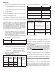
Friction loss, expressed in equivalent length of Schedule 40
pipe and based on Hazen-Williams Formula with C=120
and a flowing velocity of 15 ft/s (4.6 m/s), is:
Valve Size Equivalent Length
2” (50mm) 4.4’ (1.3 m)
2.5” (65mm) 6.0’ (1.8 m)
3” (80mm) 12.6’ (3.8 m)
These values account for the Model DDX Deluge Valve,
supply manifold tee, butterfly control valve, and small pipe/
manifold located directly above Model DDX Deluge Valve.
Shipping Weight: 2” (50 mm), 2½” (65 mm)
& 3” (80 mm) - 554 lb. (251.8 kg)
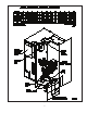
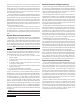
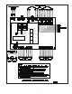
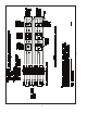
Dimensions: 2” (50mm) W x 28.9” D x 68” H
(0.61 m W x 0.73 m D x 1.73 m
H)
(Refer to Fig. 1 for additional dimensions)
Grooved end connections:
ANSI/AWWA C606 grooved inlet and outlet.
Groove Dimensions
Valve Size
Outlet
Diameter
Groove
Diameter
Groove
Width
Outlet
Face to
Groove
2” (50 mm)
2.375”
(60 mm)
2.250”
(57 mm)
5/16”
(8 mm)
3/8”
(16 mm)
2.5” (65 mm)
2.875”
(73 mm)
2.720”
(69 mm)
3” (80 mm)
3.500”
(89 mm)
3.344”
(85 mm)
1.
2.
*
3.
1.
2.
3.
4.
•
The following is a list of Technical Data Bulletins which de-
scribe the valves and devices which are used in the system:
Deluge Valve 512/513
Type D Double Interlock Preaction Trim 737
Low Air Pressure Switch System Sensor, A05-0176
Hydraulic Emergency Station (Model A) 506
Mechanical Sprinkler Alarm 612/613
Solenoid Valve 718
Alarm Pressure switch System Sensor, A05-0176
Control Panel Potter Manual #5403550
Detectors 722
Fire Alarm Devices 700
The following table provides a quick reference to various pro-
grams (found in this bulletin and the Potter Manual #5403550) that
may be utilized with a Model DDX PrePaK:
Desired
Applications
(1)
Description
Program
No.
Single Interlock
Single Hazard, 2 Alarm Zones
with 1 Waterflow Zone and 2
Supervisory Zones
Potter
Program #6
Custom
Program #1
(NYC)
Single Interlock,
Cross-Zoned
Single Hazard, Cross-Zoned, 2
Alarm Zones with 1 waterflow
Zone and 2 Supervisory Zones
Potter
Program
#7
(2)
Double Interlock
Single Hazard, 2 Alarm Zones
with 1 Waterflow Zone and 1
Supervisory Zone
Potter
Program #9
(1)
Refer to Potter Manual # 5403550 included with the PrePak, for other
programming options available.
(2)
Factory Program setting
System Design Considerations
The automatic sprinklers, releasing devices, fire detection de-
vices, manual pull stations, and signaling devices which are uti-
lized with the Reliable Model DDX 2” (50 mm), 2½” (65 mm) and
3” (80 mm) PrePaKs must be UL and/or ULC Listed or FM Ap-
proved, as applicable.
The steel enclosure and all the interconnecting piping must be
located indoors in a readily visible and accessible location and in
an area that can be maintained at a minimum temperature of 40°F
(4°C). Note: Heat tracing is not permitted. The solenoid valve
is operated and supervised by the Potter Model PFC-4410-RC
Releasing Control Panel. Details on the electrical connections of
this system to the Potter Panel can be found in the Potter Manual
#5403550, Installation, Operation and Instruction of PFC-4410-
RC Releasing Control Panel (this manual is included with other
pertinent manuals and shipped inside the enclosure). This panel
is fully zone and output programmable and may be adapted to
several applications.
System Supervising Pressure Requirements
In accordance with NFPA 13, when using the Reliable Model
DDX 2” (50 mm), 2½” (65 mm) or 3” (80 mm) PrePaK in double
interlock applications, a minimum of 7 psi (0,5 bar) pneumatic
pressure is required to supervise the sprinkler system. When ini-
tially filling the system with air, the enclosure’s door should remain
open in order to provide maximum intake air flow to the air com-