
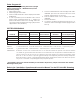
Technical data

Inspection And Testing Of Single And Double
Interlock Systems
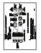
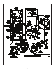
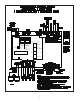
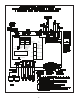
Refer to Fig. 8.
Water supply — Verify that the valve controlling wa-
ter supply to the deluge valve is opened fully and
properly monitored.
Alarm line — Verify that valve C is opened and re-
mains in this position.
Other trimming valves — Verify that valve A is
open as well as all of the pressure gauge’s ¼” 3-way
valves. Valves D, E, and H should be closed.
Ball drip valve F — Push in on the plunger to be sure
the ball check is off its seat. If no water appears, the
deluge valve’s water seat is tight. Inspect the bleed
hole in the front of the Model DDX Deluge Valve for
leakage.
System pneumatic pressure — Verify that system
air pressure is between 7 and 10 psi (0,5 bar 0,7
bar). Check the Pressure Maintenance Device for
leakage and proper pressure.
Releasing device — Check the outlet of the releas-
ing device (i.e., solenoid valve or the Model B Manual
Emergency Station, valve D) for leakage. Also verify
that tubing drain lines from releasing devices are not
pinched or crushed which could prevent proper re-
leasing of the deluge valve.
Testing alarms — Open valve E permitting water
from the supply to flow to the alarm pressure switch
and to the mechanical sprinkler alarm (if present).
After testing, close this valve completely. Push in on
the plunger of ball drip valve F until all of the water
has drained from the alarm line.
Operational test — Open the Model B Manual Emer-
gency Station, valve D only, OR, operate the solenoid
valve by electrical actuation. This is done by oper-
ating a detector or an electric manual emergency
station. Double interlock systems also require that
the sprinkler system’s air pressure be discharged,
through the inspectors test station or other venting
means, below 4 psi (0,3 bar) before total system
operation will occur. Note: An operational test will
cause the Deluge Valve to open and flow water into
the sprinkler system.
Secure the Model B Manual Emergency Station,
valve D, in the OFF position with a nylon tie (included
with the assembly) after the deluge valve is reset.
1.
2.
3.
4.
5.
6.
7.
8.
9.
Testing The Model DDX PrePaK Without
Causing Water Flow
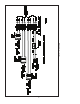
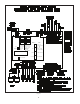
Refer to Fig. 8.
Close the main valve controlling water supply to the deluge
valve and open drain valve B.
Verify that valve A is open, allowing water to enter the push-
rod chamber.
Operate the detection system - Operate a cross-zoned re-
leasing control panel by operating two detectors. For dou-
ble interlock applications, close valve J and open valve H.
Doing so will discharge the sprinkler system’s air pressure.
Step #3 should result in a sudden drop of water pressure
in the deluge valve’s push-rod chamber via an energized
solenoid valve.
Reset the detection system - Reverse the detection system
operations performed in Step #3 above. Note: All detec-
tion devices must be reset before the Potter PFC-4410-RC
Releasing Control Panel can be reset.
Proceed according to the directions listed in the “Resetting
Single And Double Interlock Systems” section of this bul-
letin.
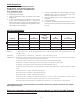
Draining Excess/Condensate Water From
The System
Refer to Fig. 8.
Close the main valve controlling water supply to the deluge
valve. Also, close valve A and open the main drain valve,
valve B.
Open the condensate drain valve, valve H, until all of the
water (if any) drains completely. Note: Be sure not to keep
valve H open for an extended period of time because that
will cause enough system air to bleed off, thereby activat-
ing the system pressure switch and causing an potentially
undesirable alarm condition.
Close the main drain valve B. Allow the system’s air pres-
sure to return to its previous level. Open valve A first, and
then open the main valve controlling the water supply to the
deluge valve.
1.
2.
3.
4.
5.
6.
1.
2.
3.
13.