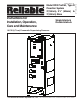
Bulletin 740 Rev. B Instructions for Installation, Operation, Care and Maintenance Single Interlock Double Interlock 10 PSI (0,7 bar) Pneumatic Supervising Pressure The Reliable Automatic Sprinkler Co., Inc., 103 Fairview Park Drive, Elmsford, New York 10523 Bulletin 740 Rev.
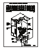
General Description The Reliable Model DDX 2” (50 mm), 2½” (65 mm) and 3” (80 mm) PrePaKs are completely self-contained, supervised preaction systems that can be readily installed within a floor space of 4.5 ft2 (0.42 m2) (not including door swing). Installation of the PrePaK (not including exterior devices, i.e.
Fig. 1 3.
Approvals 1. Underwriters Laboratories, Inc. Listed and Certified for Canada* (cULus) as an assembled unit in the “Special System Water Control Valves Assembled Units” category, (VKYL). 2. Factory Mutual (FM) Approved, as PrePak Single Interlock and Double Interlock Preaction Systems. * Electrical devices and control panel must be specified to meet Canadian requirements. This option is available. 3.
pressor. The air compressor is connected to an 2 gallon (9.1 liter) ASME rated storage tank. This tank functions as a reservoir, providing make-up air to compensate for small, intermittent leaks in the sprinkler system. It should be noted that significant leaks may overburden this storage tank, thereby causing the air compressor to continuously cycle on and off. The Pressure Maintenance Device supplied with the system (refer to Fig.
Energizing the releasing solenoid valve allows the deluge valve’s push-rod chamber to be vented to drain through its outlet. Since the pressure cannot be replenished through the inlet restriction as rapidly as it is vented though the outlet, the push-rod chamber pressure falls rapidly. When the push-rod chamber pressure drops below one-third of the supply pressure, the opening force acting beneath the clapper becomes greater than the push-rod force acting on the lever. This causes the clapper to open.
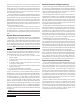
RED O UTPUT LED STEADY: ABORT RUN PROGRAM ZONE 1 OUTPUT 1 ZONE 2 OUTPUT 2 ZONE 3 OUTPUT 3 ZONE 4 OUTPUT 4 AC POW ER S U P 1 /A B O R T PO W ER TBL S U P E R V IS O R Y 2 SYSTEM TBL C O M M O N A LA R M SUP TBL GROUND F A U LT A L A R M S ILE N C E STEADY: D IS C H A R G E D F L A S H IN G : P R E -D IS C H A R G E RUN MODE PROGRAM MODE S C R O L L -U P B U Z Z E R S ILE N C E SET SELECT F U N C T IO N } LAM P TEST S C R O L L -D O W N B U Z Z E R S ILE N C E S IG N A L S ILE N C E
Fig. 3 8.
Fig. 4 9.
. Fig.
. Fig.
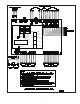
. Figure 7 — Wiring Diagram
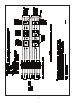
Inspection And Testing Of Single And Double Interlock Systems Testing The Model DDX PrePaK Without Causing Water Flow Refer to Fig. 8. 1. Water supply — Verify that the valve controlling water supply to the deluge valve is opened fully and properly monitored. 2. Alarm line — Verify that valve C is opened and remains in this position. 3. Other trimming valves — Verify that valve A is open as well as all of the pressure gauge’s ¼” 3-way valves. Valves D, E, and H should be closed. 4.
Fig. 8 14.
Potter Program #6 Single Interlock Programming Instructions (Single Hazard; 2 Alarm Zones, 1 Waterflow Zone, and 2 Supervisory Zones) 1. Apply power to panel. 2. Slide the program switch down. 3. Press the FUNCTION button until the display reads “PASSWORD=000.” 4. To enter a password, press the SELECT button until the proper number is displayed above the “^” symbol; then press the SET button to move to the next digit. After entering the third number the display will change.
RED O UTPUT LED STEADY: ABO RT ZONE 1 OUTPUT 1 ZONE 2 OUTPUT 2 ZONE 3 OUTPUT 3 ZONE 4 OUTPUT 4 AC POW ER RUN PROGRAM S U P 1 /A B O R T PO W ER TBL S U P E R V IS O R Y 2 SYSTEM TBL C O M M O N A LA R M SUP TBL GROUND F A U LT A L A R M S ILE N C E STEADY: D IS C H A R G E D F L A S H IN G : P R E -D IS C H A R G E RUN MODE PROGRAM MODE S C R O L L -U P B U Z Z E R S ILE N C E SET SELECT F U N C T IO N } LAM P TEST S C R O L L -D O W N B U Z Z E R S ILE N C E S IG N A L S ILE N C E
Potter Program #7 Single Interlock Programming Instructions (Single Hazard - Cross-Zoned, 2 Alarm Zones, 1 Waterflow Zone and 2 Supervisory Zones) 1. Apply power to panel. 2. Slide the program switch down. 3. Press the FUNCTION button until the display reads “PASSWORD = 000.” 4. To enter a password, press the SELECT button until the proper number is displayed above the “^” symbol; then press the SET button to move to the next digit. After entering the third number the display will change.
R E D O U T P U T LE D S T E A D Y : A B O R T ZONE 1 OUTPUT 1 ZONE 2 OUTPUT 2 ZONE 3 OUTPUT 3 ZONE 4 OUTPUT 4 AC POW ER RUN PROGRAM S U P 1 /A B O R T POW ER TBL S U P E R V IS O R Y 2 SYSTEM TBL C O M M O N A LA R M SUP TBL GROUND F A U LT A LA R M S IL E N C E STEADY: D IS C H A R G E D F LA S H IN G : P R E -D IS C H A R G E RUN MODE PROGRAM MODE S C R O L L-U P B U Z Z E R S ILE N C E SET SELECT F U N C T IO N } LAM P TEST S C R O L L-D O W N B U Z Z E R S ILE N C E S IG N A L
Potter Program #9 Double Interlock Programming Instructions (Single Hazard, Cross Zoned, 2 Alarm Zones (1 Detection & 1 Low Air), 1 Waterflow Zone, and 1 Supervisory Zone) 1. Apply power to the panel. 2. Slide program switch down. 3. Press the FUNCTION button until display reads “PASSWORD=000.” 4. To enter a password, press the SELECT button until the proper number is displayed above the “^” symbol; then press the SET button to move to the next digit.
R E D O U T P U T LE D S T E A D Y : A B O R T RUN PROGRAM ZONE 1 OUTPUT 1 ZONE 2 OUTPUT 2 ZONE 3 OUTPUT 3 ZONE 4 OUTPUT 4 AC POW ER S U P 1/A B O R T POW ER TBL S U P E R V IS O R Y 2 SYSTEM TBL CO M M O N ALARM SUP TBL GROUND F A U LT A LA R M S ILE N C E STEADY: D IS C H A R G E D F LA S H IN G : P R E -D IS C H A R G E RUN MODE PROGRAM MODE S C R O L L-U P B U Z Z E R S IL E N C E SET S E LE C T F U N C T IO N } LAM P TEST S C R O L L -D O W N B U Z Z E R S IL E N C E S IG N A
Potter Program #10 Double Interlock Programming Instructions (Single Hazard, Cross Zoned, 3 Alarm Zones (2 Detection & 1 Low Air), 1 Waterflow Zone, and 1 Supervisory Zone) 1. Apply power to the panel. 2. Slide program switch down. 3. Press the FUNCTION button until the display reads “PASSWORD=000.” 4. To enter a password, press the SELECT button until the proper number is displayed above the “^” symbol, then press the SET button to move to the next digit.
RED O UTPUT LED STEADY: ABORT ZONE 1 OUTPUT 1 ZONE 2 OUTPUT 2 ZONE 3 OUTPUT 3 ZONE 4 OUTPUT 4 AC POW ER RUN PROGRAM S U P 1 /A B O R T PO W ER TBL S U P E R V IS O R Y 2 SYSTEM TBL C O M M O N A LA R M SUP TBL GROUND F A U LT A L A R M S ILE N C E STEADY: D IS C H A R G E D F L A S H IN G : P R E -D IS C H A R G E RUN MODE PROGRAM MODE S C R O L L -U P B U Z Z E R S ILE N C E SET SELECT F U N C T IO N } LAM P TEST S C R O L L -D O W N B U Z Z E R S ILE N C E S IG N A L S ILE N C E
Custom Program #1 11. Press the SELECT button until the display reads “PROGRAM #0.” 12. Press the SET button. 13. Press the FUNCTION button until the display reads “OUTPUT 1: INDICATING.” 14. Press the SET button until the display reads “OUTPUT #2: INDICATING.” 15. Press the SELECT button until the display reads “TROUBLE BELL.” Press the SET button. 16. Press the FUNCTION button until the display reads “ZONE 1 OUTPUTS.
RED O UTPUT LED STEADY: ABORT ZONE 1 OUTPUT 1 ZONE 2 OUTPUT 2 ZONE 3 OUTPUT 3 ZONE 4 OUTPUT 4 AC POW ER RUN PROGRAM S U P 1 /A B O R T PO W ER TBL S U P E R V IS O R Y 2 SYSTEM TBL C O M M O N A LA R M SUP TBL GROUND F A U LT A L A R M S ILE N C E STEADY: D IS C H A R G E D F L A S H IN G : P R E -D IS C H A R G E RUN MODE PROGRAM MODE S C R O L L -U P B U Z Z E R S ILE N C E SET SELECT F U N C T IO N } LAM P TEST S C R O L L -D O W N B U Z Z E R S ILE N C E S IG N A L S ILE N C E
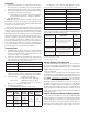
Ordering Information: Model DDX 2” (50 mm), 21/2” (65 mm) and 3” (80 mm) PrePAK Part Number Code Key 2 25 3 2 = PrePaK Assembly with 2” (50 mm) Grooved Ends Model DDX Deluge Valve 25 = PrePaK Assembly with 2½” (65 mm) Grooved Ends Model DDX Deluge Valve 175 250 1 2 175 = 175 psi (12,1 bar) System Pressure Rating 1 = cULus / FM Approved Pressures Switches 250 = 250 psi (17,2 bar) System Pressure Rating 2 = ULC Approved Pressures Switches Pressure Switch & Approvals Pressure Rating 0 1 2 0 = No Air C
SOLENOID VALVE INSPECTIONS, TESTS AND MAINTENANCE WARNING: THE OWNER IS RESPONSIBLE FOR MAINTAINING THE FIRE PROTECTION SYSTEM IN PROPER OPERATING CONDITION. ANY SYSTEM MAINTENANCE OR TESTING THAT INVOLVES PLACING A CONTROL VALVE OR DETECTION SYSTEM OUT OF SERVICE MAY ELIMINATE THE FIRE PROTECTION OF THAT SYSTEM. PRIOR TO PROCEEDING, NOTIFY ALL AUTHORITIES HAVING JURISDICTION. CONSIDERATION SHOULD BE GIVEN TO EMPLOYMENT OF A FIRE PATROL IN THE AFFECTED AREA.