
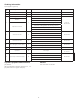
Technical data

7.
Resetting Single Interlock System
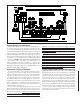
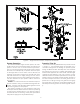
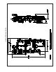
Refer to Figure 3.
1. Close the valve controlling water supply to the riser
assembly and shut off the system air supply.
2. Open both drain valves and the manual emergency
station valve to drain the system through the riser as-
sembly.
3. Open any low point drain valves and vents through-
out the system, closing all drain valves and vents
when draining of water has stopped.
4. Inspect and replace any portion of the sprinkler sys-
tem and detection system exposed to fire conditions.
Reset detectors and Potter PFC-4410-RC Releasing/
Control Panel (refer to Bulletin 700). This action will
also close (reset) the solenoid valve.
5. Reset the riser assembly in accordance with Bulletin
507, “Model H Deluge Riser Assembly Instructions
for Installation, Operation, Care and Maintenance.”
6. Restore the system supervisory by activating the
Reliable Air/Nitrogen Pressure Maintenance Device
(Refer to Bulletin 254).
7. Verify that the supervised control valve is open, and
proper monitoring has been restored. Also verify
there is no leakage from the automatic drain valve,
thereby confirming that supply water is not leaking
into the system.
Inspection and Testing
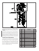
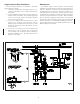
Refer to Figures 3 and 4.
1. Water supply - be sure the valve controlling water
supply to the riser assembly is open fully and moni-
tored properly.
2. Other trimming valves - check that all pressure gauge
valves are open. Verify that gauges are indicating
proper supervisory and water pressure readings.
3. Check that system supervisory pressure is approxi-
mately 7 psi or 0.48 bar.
4. Test water flow alarm devices by opening alarm test
valve. After closing alarm test valve, push plunger
into automatic drain valve to verify that all water is
drained from the alarm line.
5. The automatic drain valve monitors the possibility
of leakage past the solenoid valve or manual emer-
gency station valve. Push the plunger inward, and if
no water discharges and the drip cup is dry, the riser
assembly is leak tight.
6. 6.
7. Operation test - operate by electrical actuation (re-
fer to Bulletin 700, ”Special Hazards & Special Sys-
tems,” for details).
Note: An operational test will cause water flow throughout
the riser assembly and into the system. Where difficulty in
performance is experienced, contact Reliable Technical
Services before any field adjustment is to be made.
Testing Detection System Without
Causing Water Flow
Refer to Figure 3 and 4.
1. Close the isolating valve controlling water supply
to the riser assembly, and note the water pressure
gauge reading. Also, close supervisory pressure
supply line to the system.
2. Operate the detection system - operate a cross-
zoned releasing control panel by operating two de-
tectors (refer to Bulletin 700, “Special Hazards &
Special Systems” for details).
3. Operation of the detection system must result in a
sudden drop of water pressure as the solenoid
valve opens. When the water pressure gauge drops
to zero; open main drain valve, bypass drain valve
and manual emergency station valve until all water
above the Isolating Valve drains away.
4. Reset detection system - reverse operations per-
formed in Step “2” above. All detection devices must
be reset before the Potter PFC-4410-RC Releas-
ing/Control Panel can be reset. The solenoid valve
closes when the releasing panel is reset. Close the
bypass drain valve and manual emergency station
valve.
5. Open slightly the isolating valve controlling water
supply to the riser assembly, closing the main drain
valve when water flows steadily. Open slowly but
fully the isolating valve and monitor it properly.
6. It is necessary to shut down the supervisory pres-
sure supply (ref. Step “1”) during testing; otherwise,
low pressure annunciation can occur when the drain
valves are opened in Step “3”. Restore the supervi-
sory pressure to 35 oz/in
2
(2 psi or 0,14 bar) at this
time.