
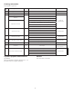
Technical data

6.
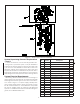
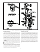
Single Interlock Riser Installation
The recommended sequence of installation is as follows
(refer to Figures 2 and 3):
1. Install the Deluge Riser Assembly portion in ac-
cordance with Bulletin 507, “Model H Deluge Riser
Assembly.
2. Install the Model G Right Check™ Valve above the
Model H Riser Assembly using threaded/grooved
reducers and rigid grooved couplings supplied
with the Preaction Trim Kit.
3. Connect the bypass drain line between the 1 NPT
(R1) port on the Right Check™ Valve and the
Model H Riser Assembly after removing its ¾” NPT
(R¾) plug. Follow instructions provided in the Pre-
action Trim Kit.
4. Connect the air supply line form the Reliable Air
Maintenance Device (Model B-SI Compressor
Panel, Model C-SI Compressor Panel, NS-PaK or
Model A-2 AMD) to the ½” NPT (R 1/2) port on the
Right Check
TM
Valve.
Maintenance
The Reliable Single Interlock System and associated
equipment shall periodically be given a thorough inspection
and test. NFPA 25, Inspection, Testing and Maintenance
of Water Based Fire Protection Systems, provides mini-
mum maintenance requirements. A single interlock system
should be tested, operated, cleaned and inspected at least
annually, and parts replaced as required. Refer to Bulletin
507 for information regarding maintenance of the solenoid
valve and the manual emergency station valve. Bulletin 254
provide information on the Reliable Air/Nitrogen Automatic
Pressure Maintenance Devices. Bulletin 806 describes the
Model G Right Check™ Valve.
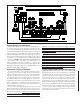
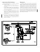
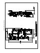
Figure 4 — Single Interlock Preaction System