
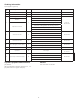
Technical data

5.
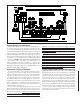
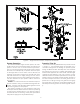
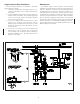
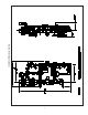
Figure 3 — Single Interlock Preaction, Component Identification
System Operation
To activate a Reliable Single Interlock System, two inde-
pendent events must coexist before water can flow from the
system to the fire. First, an electrical detector (two detec-
tors in a cross-zoned system) must activate to fill the system
with water, and subsequently, a sprinkler head must open
to discharge water on the fire. When a fire is detected, the
releasing control panel energizes the solenoid valve open
and water flows from the supply through the riser assem-
bly to the system and to the alarm initiating pressure switch.
The valve maintains its open position until the solenoid is
de-energized.
Caution: The solenoid valve must be maintained open to
prevent automatic closing of the Model H Deluge Riser As-
sembly. The Potter PFC-4410-RC Releasing/Control Panel
has a latching feature for this purpose.
After system shutdown, the riser assembly is easily reset
without special tools. Restore detection devices by resetting
or replacing any operated device. Once detection devices
are restored, reset the releasing control panel (see Bulletin
700) and the supply pressure (see Bulletin 507).
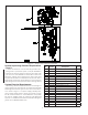
Preaction Trim Kit
The Preaction Trim Kit (P/N 6501200112) consists of items
1 through 17. The illustrated (Figure 2) assembly has a
convenient arrangement for draining the sprinkler system
through the Model H Riser Assembly drain line. Assemble
the Preaction Trim Kit using a suitable Teflon-based pipe
thread sealant applied to each male thread. Assemble rigid
couplings by first applying a thin coat of silicone or other
lubricant that does not contain hydrocarbons to the lips and
outside surfaces of the gasket. Position gaskets uniformly on
the valve and adjacent reducers so that all grooves are ex-
posed. Place coupling housings over gaskets and engage
the housing keys in the grooves. Insert bolts and tighten nuts
alternately until housing halves are drawn together uniform-
ly.