
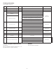
Technical data

3.
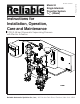
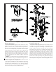
Figure 1
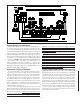
System Design Considerations
The automatic sprinklers, air compressor, releasing devic-
es, electric releasing control equipment, fire detection de-
vices, manual pull stations, and signaling devices which are
utilized with the Reliable Single Interlock System must be UL
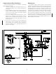
and/or ULC listed, as applicable. The Single Interlock Preac-
tion Assembly (Figure 2) and all interconnecting piping must
be located in a readily visible and accessible location and in
an area which can be maintained at a minimum temperature
of 40°F (4°C). NOTE: HEAT TRACING IS NOT PERMITTED.
The solenoid valve is operated and supervised by the
electric releasing control panel. Details on connecting the
electrical portion of this system to a Potter PFC-4410-RC Re-
leasing/Control Panel can by found in Reliable Bulletin 700,
“Specail Hazards & Special Systems.”
Hydrostatic Testing of Systems
As required by NFPA 13, fire sprinkler systems with work-
ing pressures up to and including 150 psi are to be hydro-
statically tested at a water pressure of 200 psi and maintain
that pressure without loss for two hours. Fire sprinkler sys-
tems with working pressures above 150 psi are required to
be hydrostatically tested at 50 psi above the system work-
ing pressure and maintain that pressure without loss for two
hours. In addition to the hydrostatic tests described above,
dry pipe and double interlock preaction systems require an
additional low pressure air test.
In some cases, hydrostatic testing (in accordance with the
NFPA 13 requirements noted above) will result in pressures
that exceed the working pressure of the valve and trim kit for
the two-hour test period. The valve and applicable trim kit
have been tested, approved and listed under these condi-
tions and as such, hydrostatic testing in accordance with
NFPA 13 is acceptable. In addition, the clapper can remain
in the closed position and the trim kit need not be isolated,
as each has been designed to withstand hydrostatic testing
as required by NFPA 13.
Hydrostatically testing the valve and trim to pressures
higher than their rating is limited to the hydrostatic test as ref-
erenced by NFPA 13. It does not address the occurrence(s)
of a “water hammer” effect, which can indeed damage the
valve. A “water hammer” in the water supply piping of the
valve can create pressures in excess of the rated pressure
and should be avoided by all necessary means. This con-
dition may be created from improper fire pump settings,
underground construction work, or an improper venting of
trapped air in the water supply piping.
System Supervising Pressure Requirements
A Reliable Model B-SI Air Compressor Panel or Model C-SI
Air Compressor Panel is used to maintain the supervising
pneumatic pressure. The Air Compressor Panel contains an
integral low air pressure warning light. The Reliable super-
visory pressure sources are factory set to transfer contact
when the supervisory pressure falls below approximately 4
psi (0.48 bar). The Pressure Maintenance Device is a super-
visory pneumatic supply for use where a clean, dependable
and continuous (7 days per week at 24 hours per day) plant-
wide compressed air or dry nitrogen gas source is available
in a 40 to 100 psi (2,8 to 6,9 bar) pressure range. Detailed
information on these supervisory pressure sources can be
found in Reliable Bulletin 254.