
Technical data

2.
General Description
Reliable Single Interlock Preaction Systems are designed
for water sensitive areas which require protection from inad-
vertent water flow into the sprinkler system piping. Sprinkler
piping in single interlock systems can effectively be super-
vised by means of a Reliable Model B-SI Air Compressor
Panel, a Reliable Model C-SI Air Compressor Panel or the
Reliable Model NS-PaK. Loss of supervising pneumatic
pressure, due to a damaged sprinkler or pipe line, will not
cause water to flow through a control valve and into the sys-
tem piping. A significant loss of pneumatic pressure will ac-
tivate a trouble-annunciating device when system pressure
falls below the supervisory pressure switch settings (4 psi for
the B-SI and C-SI Air Compressor Panels).
When one electrical detector senses the presence of fire,
the electrical releasing control panel activates fire alarm de-
vices and latches the solenoid releasing valve in the open
position (note that arranging detectors in a cross-zoned pat-
tern will require operation of two detectors before the sole-
noid valve can open). The solenoid valve, when closed, is
preserving supply water pressure in the inlet of the Reliable
Model H Deluge Riser Assembly. Actuating the solenoid
valve releases that water pressure, allowing water flow into
the sprinkler system in readiness for the subsequent opera-
tion of a sprinkler.
To fully operate a cross-zoned single interlock system, two
electrical detectors must activate and a sprinkler must open.
During the early stages of a fire, smoke or heat activates the
first detector which causes the control panel to produce a
local alarm and an alarm at the main fire alarm panel. Electri-
cal relays inside the releasing control panel can be used to
shut down air moving equipment or activate security doors
and other electrical devices when the panel goes into this
first alarm condition. Subsequent activation of a second,
nearby or adjacent, detector will cause the panel to energize
the solenoid valve open and release water into the sprinkler
piping. Water flowing into the sprinkler piping will simulta-
neously produce water pressure that causes the transfer
of contacts in the pressure switch mounted in the Riser As-
sembly. This switch can electrically initiate the shutdown or
startup of equipment, such as computers or other second
alarm devices. The flow of water into the sprinkler piping ef-
fectively converts the dry system into a wet pipe system. In
the event the fire subsequently produces sufficient heat to
operate a sprinkler head, water will flow from that sprinkler,
controlling or suppressing the fire.
The major benefits of a single interlock preaction system,
when compared with a wet pipe system, are as follows:
A. A fire alarm sounds prior to the operation of a
sprinkler, which may enable extinguishing the
fire by handheld means before the operation of
any sprinkler head occurs.
B. A trouble annunciator signals whenever the in-
tegrity of piping or sprinklers is accidentally or
intentionally disturbed; however, no water flow or
water damage will result at that time.
C. Speedy detection and an early fire alarm are pro-
vided by fire detectors, without the delay associ-
ated with water delivery time in the event of a fire.
Note that with a wet pipe system, the fire alarm is
delayed until after water has begun flowing from
an operated sprinkler head.
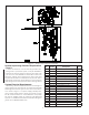
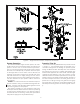
A Hydraulic Manual Emergency Releasing Station is stan-
dard equipment in the Model H Riser Assembly. It is identi-
fied by a nameplate attached above the releasing valve.
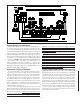
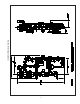
A Preaction Trim Kit is available to provide a bypass drain
line and to attach the air or nitrogen supply required to su-
pervise the preaction system at 7 psi (0.48 bar). This kit in-
cludes a UL Listed Reliable Model G Right Check Checkä
supplied with rigid grooved pipe couplings, as illustrated in
Figure 2.
Approvals
The 1½” Reliable Single Interlock Preaction System is Un-
derwriters Laboratories, Inc. Listed in the Special System
Water Control Valves - Deluge Type (VLFT) category. It is
also Listed by Underwriters’ Labortory of Canada. The Mod-
el G Right Check™ Valve is Listed by UL and ULC. NYC
MEA 258-93-E applies to both the Model H Assembly and
the Model G Right Checkä Valve.
Technical Data
The 1½” Reliable Single Interlock Preaction System, with
associated trim, is rated for a minimum supply pressure of
20 psi (1,4 bar) and a maximum supply pressure of 175 psi
(12 bar).
Friction loss, expressed in equivalent length of Sch. 40
pipe and based on Hazen & Williams formula with C=120,
and a flowing velocity of 15 ft/s (4.6 m/s), is 29 ft. (8.84 m)
for the Model H Riser Assembly, and 7 ft. (2.1 m) for the 2½”
(65mm) Model G Right Checkä Valve.
Shipping Weights:
Model H Riser Assembly 52 lbs. (23.6kg)
Model B-SI Compressor Panel 42 lbs (19.1kg)
Model C-SI Compressor Panel 42 lbs (19.1Kg)
NS-PaK 40 lbs (18.2Kg)
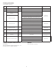
The following list of Technical Data Sheets describe the
valves and devices which are used in this system.
Deluge Riser Assembly 507
Water Flow Pressure Alarm Switch A05-0176
Pressure Maintenance Device 254
Air Compressor Panel 254
Releasing/Control Panel Potter #5403550
Electric Emergency Station 700
Thermal Detectors 700
Fire Alarm Devices 722
Automatic Nitrogen Reg. Device 253
Model G Right Check™ Valve 806