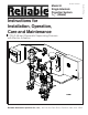
Bulletin 719 Rev. I Instructions for Installation, Operation, Care and Maintenance 7 PSI (0.48 bar) Pneumatic Supervising Pressure with Electric Actuation Reliable Automatic Sprinkler Co., Inc., 103 Fairview Park Drive, Elmsford, New York 10523 Bulletin 719 Rev.
General Description Reliable Single Interlock Preaction Systems are designed for water sensitive areas which require protection from inadvertent water flow into the sprinkler system piping. Sprinkler piping in single interlock systems can effectively be supervised by means of a Reliable Model B-SI Air Compressor Panel, a Reliable Model C-SI Air Compressor Panel or the Reliable Model NS-PaK.
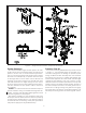
System Design Considerations Figure 1 The automatic sprinklers, air compressor, releasing devices, electric releasing control equipment, fire detection devices, manual pull stations, and signaling devices which are utilized with the Reliable Single Interlock System must be UL and/or ULC listed, as applicable.
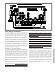
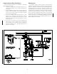
Figure 2 — Single Interlock Preaction Assembly System Supervising Pressure Requirements - Cont’d Item No. In some circumstances, such as when dry sprinklers are being used in a preaction system, it may be desirable to supervise the preaction system at air pressures higher than 7 psi. For such cases, Reliable recommends the use of the NS-Pak or a Model A-2 air maintenance device with either a System Sensor EPS-10 or EPS-40 low air pressure switch.
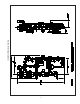
Figure 3 — Single Interlock Preaction, Component Identification System Operation Preaction Trim Kit To activate a Reliable Single Interlock System, two independent events must coexist before water can flow from the system to the fire. First, an electrical detector (two detectors in a cross-zoned system) must activate to fill the system with water, and subsequently, a sprinkler head must open to discharge water on the fire.
Single Interlock Riser Installation Maintenance The recommended sequence of installation is as follows (refer to Figures 2 and 3): 1. Install the Deluge Riser Assembly portion in accordance with Bulletin 507, “Model H Deluge Riser Assembly. 2. Install the Model G Right Check™ Valve above the Model H Riser Assembly using threaded/grooved reducers and rigid grooved couplings supplied with the Preaction Trim Kit. 3.
Resetting Single Interlock System Testing Detection System Without Causing Water Flow Refer to Figure 3. 1. Close the valve controlling water supply to the riser assembly and shut off the system air supply. 2. Open both drain valves and the manual emergency station valve to drain the system through the riser assembly. 3. Open any low point drain valves and vents throughout the system, closing all drain valves and vents when draining of water has stopped. 4.
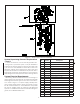
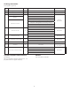
Ordering Information Specify (Ref. Figure 4): Item No. Component Part Mfr.
. Installation Dimensions in Inches
SOLENOID VALVE INSPECTIONS, TESTS AND MAINTENANCE WARNING: THE OWNER IS RESPONSIBLE FOR MAINTAINING THE FIRE PROTECTION SYSTEM IN PROPER OPERATING CONDITION. ANY SYSTEM MAINTENANCE OR TESTING THAT INVOLVES PLACING A CONTROL VALVE OR DETECTION SYSTEM OUT OF SERVICE MAY ELIMINATE THE FIRE PROTECTION OF THAT SYSTEM. PRIOR TO PROCEEDING, NOTIFY ALL AUTHORITIES HAVING JURISDICTION. CONSIDERATION SHOULD BE GIVEN TO EMPLOYMENT OF A FIRE PATROL IN THE AFFECTED AREA.