
Technical data

23.
2. COMPONENT DESCRIPTIONS
2.1 Main System Control Valves
Special systems, whether deluge, preaction or low pressure dry, control the release of water to the protected
area until a particular condition or set of conditions is met. The main system control valve is defined as the
valve which separates the pressurized water supply source from piping in the protected area. Two types of
main system control valves are used for Reliable Special Systems.
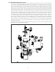
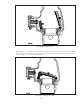
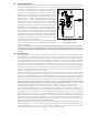
2.1.1 Model H
The Reliable Model H 1½” (40mm) Riser Assembly incorporates a normally closed, quick-opening
hydraulically operated diaphragm actuated solenoid valve as the system control valve for both deluge
and preaction fire protection systems. The Model H is listed by Underwriter Laboratories (UL) but is
NOT Factory Mutual Approved. (If Factory Mutual Approval is required, refer to the Model DDX Deluge
Valve in section 2.1.2 below.) The trim is factory assembled for every Model H Deluge Riser Assembly.
Three field piping connections are required: an appropriate water supply, the system piping connec-
tion, and a ¾” NPT drain line connection.
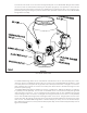
When in the normal condition (de-energized), fire protection system supply water is held at the so-
lenoid valve inlet. When the valve is energized by power from a releasing panel, the solenoid valve
opens and water flows through the deluge riser assembly into the fire protection system piping. Alarm
devices are activated upon the flow of wa-
ter into the sprinkler system piping.
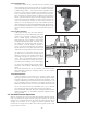
After the system is shut down and drained,
the valve is easily reset without special
tools. When the detection devices have re-
turned to ready condition, the deluge riser
assembly is placed back in service by sim-
ply resetting the releasing panel. This easy
reset feature of the Model H Riser Assembly
provides a means for simple, economical
system testing which is an essential facet
of a good maintenance program.
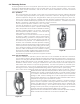
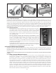
The Reliable Model H Riser Assembly may
be used in any application requiring a del-
uge or preaction system with an electrical
detection system. Actuation of the solenoid
valve may be achieved with various types of
detectors and a listed release control pan-
el. Care should be taken to ensure that all
components are listed for compatibility and
for the intended application. Electrical con-
nections are required between the listed re-
lease control panel and the solenoid valve,
system control valve supervisory switch,
the water flow alarm pressure switch, and
low pressure supervisory switch (when ap-
plicable).
Figure 22