
Technical data
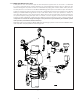
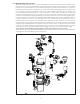
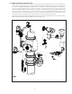

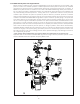

1.2.2 Model DDX Dry Pilot Line Single Interlock
Where freezing conditions exist, or where height/distance limits of wet pilot lines are exceeded, a dry
pilot line can be used. Closed sprinklers or fixed-temperature-release pilot line detectors are installed
throughout the protected area on small diameter piping that contains pressurized air or nitrogen. A
Model LP Dry Pilot Actuator is installed on the outlet of the Model DDX Deluge Valve push-rod cham-
ber. This device provides a separation between the hydraulically pressurized push-rod chamber and
the pneumatically pressurized pilot line. The dry pilot line is a pneumatic extension of the push-rod
chamber. Upon activation of a pilot line sprinkler or pilot line detector, pneumatic pressure is released
from the piping allowing the dry pilot actuator to vent and release hydraulic pressure from the push-rod
chamber. This allows the Model DDX Deluge Valve to open and fill the system piping in the protected
area. Alarm devices are activated upon the flow of water into the sprinkler system piping. In the event
the fire continues to grow, individual fire sprinklers in the protected area will be activated similar to a wet
pipe system. A single pneumatic supply can serve the dry pilot line and supervise the piping system
(required when there are more than 20 sprinklers on the system). Pneumatic pressure can be provided
from a tank-mounted compressor, plant air system, or nitrogen cylinders, and must be maintained by
a Reliable Model A-2 listed pressure maintenance device. To prevent accidental system activation and
monitor the integrity of the system piping, pneumatic pressure is monitored by a pressure switch* that
will notify the owner in the event of falling pressure due to sprinkler damage, pipe damage, or failure of
the compressed gas system.
**Note: System Sensor Model EPS 10-2 Pressure Switch is provided with the dry pilot line trim.
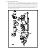
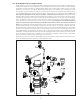
Approvals and technical data for Model DDX dry pilot line single interlock preaction systems can be
found on Reliable Automatic Sprinkler Company Bulletin 749.
10.
Figure 8