
Instruction manual


6.
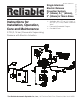
After system shutdown, resetting the Model DDX Deluge
Valve is quite simple. Doing so only requires pushing in and
turning the reset knob at the rear of the valve (see Fig.1).
The external reset feature of the Model DDX Deluge Valve
provides a means for simple, economical system testing,
which is one essential facet of a good maintenance program.
The external reset feature does not, however, eliminate an-
other important facet of good maintenance, namely, periodic
cleaning and inspection of the internal valve parts.
In the event that water builds up inside the valve due to
condensate from the air supply system or water left inside
from valve system testing, a drain is available for venting. Af-
ter closing the main supply valve, a small valve over the drain
cup can be opened slightly until the water inside the valve
body and the main pipe column has drained. See the sec-
tion titled “Draining Excess/Condensate Water From System”
in this bulletin for the detailed procedure.
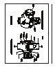
The Model B Manual Emergency Station (see Fig. 3) is also
included in the Reliable Single Interlock Preaction System
trim set. It consists of an aluminum nameplate mechanically
attached to a ball valve. The valve handle in its OFF position
is guarded against accidental turning to the ON position (and
system discharge) by a nylon cable tie provided with each
trim kit. The cable tie is inserted, as shown in Fig. 3, after the
system has been restored for operation. The nylon cable tie is
designed to allow, in case of an emergency, forceful turning
of the valve handle to the ON position. As an alternative to
the Model B Hydraulic Manual Emergency Station, the Model
A Hydraulic Manual Emergency Pull Box (see Reliable Bulle-
tin 506) is also available and can be provided as an option.
Whenever ambient temperature conditions are high, the
water temperature in the Model DDX Deluge Valve’s push-
rod chamber could possibly increase, thereby increasing the
pressure in the chamber to values exceeding the rated pres-
sure of the system. In an indoor installation where standard
room temperatures are exceeded, a pressure relief kit may
be needed. Pressure relief kit, P/N 6503050001, can be in-
stalled into the pushrod chamber’s releasing line to limit the
pressure to 175 psi (12,1 bar).
Pressurizing Line Connection
The water supply for the push-rod chamber must be pro-
vided by connection of its inlet pressurizing line to the water
supply piping. Pressurizing lines for multiple Model DDX
Deluge Valve push-rod chambers must never be manifold-
ed together, having only a single tap on the water supply
piping. Each Model DDX Deluge Valve must have its own
push-rod chamber pressurizing line connection. This con-
nection must be made on the supply side of the main water
supply control valve. This can be accomplished by:
Using a tapped connection directly below or next
to the main water supply control valve using a
welded outlet or the appropriate mechanical fit-
tings. A grooved-end outlet coupling is one way
to achieve this (see Fig. 2); or
Using a water supply control valve that has an
available threaded (NPT) supply-side tap design
to allow for a direct water supply connection to the
Model DDX Deluge Valve’s push-rod chamber.
a.
b.
Caution: Reliable’s DDX valve is designed with an inlet re-
striction built into the pushrod chamber. It is important not to
introduce additional restrictions into the direct water supply
connection or the discharge from the pushrod chamber by
installing additional valves or improperly installing the cop-
per lines used in the trim of the valve.
Hydrostatic Testing of DDX Valves and DDX
Systems
As required by NFPA 13, fire sprinkler systems with work-
ing pressures up to and including 150 psi are to be hydro-
statically tested at a water pressure of 200 psi and maintain
that pressure without loss for two hours. Fire sprinkler sys-
tems with working pressures above 150 psi are required to
be hydrostatically tested at 50 psi above the system work-
ing pressure and maintain that pressure without loss for two
hours. In addition to the hydrostatic tests described above,
dry pipe and double interlock preaction systems require an
additional low pressure air test.
In some cases, hydrostatic testing (in accordance with the
NFPA 13 requirements noted above) will result in pressures
that exceed the working pressure of the valve and trim kit for
the two-hour test period. The valve and applicable trim kit
have been tested, approved and listed under these condi-
tions and as such, hydrostatic testing in accordance with
NFPA 13 is acceptable. In addition, the clapper can remain
in the closed position and the trim kit need not be isolated,
as each has been designed to withstand hydrostatic testing
as required by NFPA 13.
Hydrostatically testing the valve and trim to pressures
higher than their rating is limited to the hydrostatic test as ref-
erenced by NFPA 13. It does not address the occurrence(s)
of a “water hammer” effect, which can indeed damage the
valve. A “water hammer” in the water supply piping of the
valve can create pressures in excess of the rated pressure
and should be avoided by all necessary means. This con-
dition may be created from improper fire pump settings,
underground construction work, or an improper venting of
trapped air in the water supply piping.
System Design Considerations
The automatic sprinklers, air compressor, releasing devic-
es, electric releasing control equipment, fire detection de-
vices, manual pull stations, and signaling devices which are
utilized with the Single Interlock Preaction System must be
UL or ULC Listed or FM Approved, as applicable.
The Deluge Valve, and all interconnecting piping must be
located in a readily visible and accessible location and in an
area that can be maintained at a minimum temperature of
40°F (4°C). Note: Heat tracing is not permitted.
Pendent sprinklers, other than dry pendents, used on pre-
action systems shall be installed on return bends per NFPA
13.
The solenoid valve is operated and supervised by the
electrical releasing/control panel. Details on the electrical
portion of this system can be found in Reliable Bulletin 700,
“ Special Hazards & Special Systems.”