
Instruction manual


15.
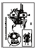
Maintenance Procedures - Model DDX
Deluge Valve
Refer to Figs. 2, 5, & 6.
Mechanical sprinkler alarm (water motor–not
shown) not operating:
This is most likely caused by a clogged screen in the
strainer of the water motor. Proceed as follows: Re-
move plug from the strainer. Remove and clean the
screen. Replace the screen and the plug, and then
tighten securely (Ref. Bulletin 613).
Leakage out of the ball drip valve E (Fig. 6).
Water leakage due to a water column above
the Deluge Valve’s clapper:
This condition can be caused by leakage past the
system side of the Model DDX Deluge Valve’s seal
faceplate subassembly (#8, Fig. 5). Be sure that
this surface is free of any type of debris. To elimi-
nate leakage due to a water column, refer to the
section in this bulletin marked “Draining Excess/
Condensate Water From System”. If the problem
continues proceed to the following section.
Leakage, air or water from the ball drip valve,
E (Fig. 6):
If system air is leaking out the ball drip valve, the
problem is either damage to the airside of the
Model DDX Deluge Valve’s seal faceplate subas-
sembly (#8, Fig. 5), seat (#29, Fig. 5),or the up-
per seat O-ring (#23, Fig. 5). If supply water is
leaking out the ball drip valve, the problem could
be caused by damage to the Model DDX Deluge
Valve’s seal faceplate sub-assembly (#8, Fig. 5),
seat (#29, Fig. 5), or lower seat O-ring (#24, Fig.
5). The following section provides instructions to
correct both conditions:
Shut down the valve controlling the water sup-
ply to the Deluge Valve and open the 1-1/4”
main drain valve B (Fig. 6). Open the water
column drain valve H (Fig. 6). Close the push
rod chamber supply valve A (Fig. 6) and open
the Model B Manual Emergency Station D
(Fig. 6).
Remove the Deluge Valve’s front (handhold)
cover (#7, Fig. 5) and inspect the seat (#29,
Fig. 5), clapper (#6, Fig. 5),and seal faceplate
subassembly (#8, Fig. 5) for damage.
If inspection indicates damage to the seal
faceplate sub-assembly (#8, Fig. 5), replace
as follows:
Remove the bump stop nut subassembly
(#10, Fig. 5) and remove the seal assembly
(#8, Fig. 5). Install a new seal assembly (#8,
Fig. 5) and thread the bump stop nut (#10,
Fig. 5) onto the threaded stud of the seal sub-
assembly (#8, Fig. 5) and tighten finger tight
plus ¼ to ½ turn.
If inspection indicates damage to the clapper
(#6, Fig. 8) only, then the clapper sub-assem-
bly can be removed as follows:
1.
2.
a.
b.
A.
B.
At the rear of the valve, disconnect the wa-
ter column drain trim section starting with the
elbow connector (#16, Fig. 2). Then remove
the ¼” angle valve (#61, Fig. 2), followed by
the ¾” x ¼” reducing bushing (#7, Fig.2). Re-
move the retaining ring (handhold cover side)
from the clapper hinge pin (#30, Fig. 5) and
push this pin through the water column drain
line and remove the clapper subassembly.
Replace the seal sub-assembly as described
previously. Inspect the clapper (#6, Fig. 5) vi-
sually before reinstalling. Reinstall in the re-
verse order making sure the clapper spacers
are in their proper position. If the seat (#29,
Fig. 5) is damaged or it is suspected that the
leakage is through the lower O-ring (#24, Fig.
5), the seat-clapper subassembly is easily re-
moved as a unit as follows:
Using Reliable P/N 6881603000 Seat Wrench,
remove the seat by unscrewing. This will loos-
en the seat-clapper-mounting ring subassem-
bly. Reach into the valve and grasp the seat-
clapper subassembly and remove it from the
valve. Visually examine all components of
the seat-clapper-mounting ring sub-assembly
replacing any component that appears dam-
aged. New O-rings (#23 & #24, Fig. 5) should
always be used for reassembly.
Reassembly:
Clean the bore of the valve body. Lubricate
the bore with O-ring grease. Lubricate and
install the O-rings (#23 & #24, Fig. 5) onto the
seat. Insert the seat-clapper-mounting ring
sub-assembly into the handhold opening of
the Deluge Valve. Align the mounting ring so
that the Lever (#15, Fig. 5) is near the pushrod
(#25, Fig. 5) and the mounting ring (#5, Fig.
5) “ears” are between the tabs of the valve
body (#1, Fig. 5).Start to tread the seat (#29,
Fig. 5) into the body by hand, then tighten
until the seat (#29, Fig. 5) with seat wrench
6881603000 until it bottoms out on the mount-
ing ring (#5, Fig. 5). Verify that the seat-clap-
per-mounting ring subassembly is in the fully
down position between the tabs of the body,
and check to see that the lever (#15, Fig. 5)
lines up with the push rod (#25, Fig. 5). Loos-
en and reassemble if necessary. Reassemble
the hand hold cover (#7, Fig. 5) and set up
the Model DDX Deluge Valve as per the sec-
tion “Resetting Model DDX Deluge Valve Sys-
tems.”
Leakage out of the push rod chamber vent hole:
A small bleed hole is located on the underside of the
push rod chamber (see Fig. 5). If there is air or water
leakage coming out of this hole, do the following:
3.