
Instruction manual


10.
ampere-hour rating, providing [60 hours – cULus Listed]
[90 hours – FM Approved]. Dry contacts shall be provided
for remote annunciation of alarm, trouble, and supervisory
panel signals. Main power supply to be a dedicated 120
VAC / 60Hz circuit.
Waterfl ow Alarm Pressure Switch
Alarm pressure switch shall be provided to indicate water
flow and provide a water flow alarm. Pressure switch shall
be [cULus Listed] [FM Approved] and of the bellows acti-
vated type enclosed in a weatherproof, 4x, NEMA 4-rated
enclosure incorporating tamper-resistant screws. There
shall be two sets of SPDT (Form C) contacts rated at 10.0
A @ 125/250 VAC and 2.5 A @ 6/12/24 VDC. The pressure
switch shall have a maximum service pressure rating of 250
psi (17,2 bar) and shall be factory adjusted to operate at a
pressure of 4 to 8 psi (0,27 to 0,55 bar) with adjustment up
to 20 psi (1,3 bar). Switch shall be provided with a ½” NPT
male pressure connection. Waterflow alarm pressure switch
shall be System Sensor EPS10-2.
Technical Data
Reliable Single Interlock Preaction Systems, with associ-
ated trim, sizes 2” (50mm), 2½” (65mm), 3” (80mm) and
76mm are rated for use at minimum water supply pressure
of 20 psi (1,4 bar) and maximum supply pressure of 250 psi
(17,2 bar). Water supplied to the inlet of the valve and to the
pushrod chamber must be maintained between 40°F (4°C)
and 140°F (60°C).
The following list of technical bulletins pertains to valves
and devices that may be used in this preaction system:
Valve Description
Deluge Valve Reliable 512/513
Hydraulic Emergency Station (Model A) Reliable 506
Solenoid Valve Reliable 718
Mechanical Sprinkler Alarm Reliable 612/613
Pressure Maintenance Device Reliable 252
Air Compressor Panel (Models B & C) Reliable 252
Releasing/Control Panel Potter #5403550
Electric Emergency Station Reliable 700
Thermal/Smoke Detectors Reliable 722
Fire Alarm Devices Reliable 700
Waterflow Pressure Alarm Switch System Sensor
A05-0176
Rated working pressure:
Valve & System - 250 psi (17,2 bar)
Factory tested to a hydrostatic pressure of 500 psi
(34,5 bar). (Valve only)
End and trim connections:
ANSI/AWWA C606 grooved inlet and outlet
Threaded openings Per ANSI B 2.1
Groove Dimensions
Valve
Size
Outlet
Diameter
Groove
Diameter
Groove
Width
Outlet
Face
to Groove
2” (50mm) 2.375” (60mm) 2.250” (57mm)
11
/
32
“
(9mm)
5
/
8
”
(16mm)
2.5” (65mm) 2.875” (73mm) 2.720” (69mm)
3” (80mm) 3.500” (89mm) 3.344” (85mm)
76mm 3.000” (76mm) 2.845” (72mm)
1.
2.
3.
•
•
Valve Exterior Color:
Valve Size Color
2” (50mm)
2.5” (65mm)
3” (80mm)
Black
76mm Red
Face to face dimensions:
2” (50mm) — 12½” (318mm)
2.5” (65mm) — 12½” (318mm)
3” (80mm) — 12½” (318mm)
76mm - 12½” (318mm)
Shipping weight:
Valve Size Weight
2” (50mm)
2.5” (65mm)
3” (80mm)
76mm
34lb. (15 kg)
Friction loss (Expressed in equivalent length of
Schedule 40 pipe, based on Hazen & Williams for-
mula with C=120 and a flow velocity of 15ft/sec (4.6
m/sec)):
Valve Size Equivalent Length
2” (50mm) 4.4’ (1.3m)
2.5” (65mm) 6.0’ (1.8m)
3” (80mm) 12.6’ (3.8m)
76mm 7.7’ (2.3m)
Installation position: Vertical
Maintenance
Reliable Single Interlock Preaction Systems and associat-
ed equipment shall periodically be given a thorough inspec-
tion and test. NFPA 25, Inspection, Testing and Maintenance
of Water Based Fire Protection Systems, provides minimum
maintenance requirements. System components shall be
tested, operated, cleaned, and inspected at least annually,
and parts replaced as required.
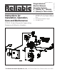
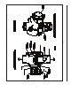
Resetting the Single Interlock Preaction
System
Refer to Figs. 2, 5, and 6.
Close the main valve controlling water supply (Fig. 6)
to the Deluge Valve and close off the air supply to the
sprinkler system.
Close the pushrod chamber supply valve, valve A
(Fig. 6).
Open the main drain valve, valve B (Fig. 6), and drain
system.
Open all drain valves and vents at low points through-
out the system, closing them when flow of water has
stopped. Open valve D (Fig. 6).
Note: The above steps accomplish the relieving
of pressure in the pushrod chamber of the Deluge
Valve.
With valve G (Fig. 6) open, push in the plunger of ball
drip valve, valve E (Fig. 6), to force the ball from its
seat, and drain any water in the alarm line.
•
4.
•
•
•
•
5.
6.
7.
1.
2.
3.
4.
5.