Bulletin 736 Rev. B Instructions for Installation, Operation, Care and Maintenance • • • Bulletin 736 Rev. B Single Interlock Electric Release Preaction System 2” (50mm), 21/2” (65mm), 3” (80mm) & 76mm Sizes Available with 175 psi (12,1 bar) or 250 psi (17,2 bar) Rated Solenoid Valve Externally Resettable Clapper One Main Drain 2 PSI (0,14 bar) Pneumatic Supervising Pressure with Electric Actuation The Reliable Automatic Sprinkler Co., Inc.
General Description Single Interlock Preaction Systems are designed for water-sensitive areas that require protection from inadvertent water flow into the sprinkler system piping. Sprinkler piping in single interlock systems can effectively be supervised by means of a Reliable Model B Air Compressor Panel or Model C Pressure Maintenance Device.
. Fig.
. Fig.
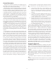
Single Interlock Electric Release Preaction Trim Parts List (Refer to Fig. 2) Item Part Number No.
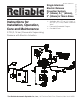
After system shutdown, resetting the Model DDX Deluge Valve is quite simple. Doing so only requires pushing in and turning the reset knob at the rear of the valve (see Fig.1). The external reset feature of the Model DDX Deluge Valve provides a means for simple, economical system testing, which is one essential facet of a good maintenance program.
System Air Pressure Requirements System Electrical Requirements A Reliable Model B Air Compressor Panel or Model C Pressure Maintenance Device is used to maintain the system pneumatic pressure at approximately 35 oz/in2 (2.2 psi or 0,2 bar). The air compressor panel contains an integral low air pressure warning light, while the pressure maintenance device requires a separate annunciating device to be connected to the low pressure switch.
. Fig.
Single Interlock Preaction System– Electric Release Trim Engineering Specifications Supervisory Air Supply Options Owner’s Air supply Single interlock preaction system air pressure shall utilize low supervisory air pressure. Air supply shall be provided by an owner supplied air system in conjunction with a [cULus Listed] [FM Approved] automatic low air pressure maintenance device.
ampere-hour rating, providing [60 hours – cULus Listed] [90 hours – FM Approved]. Dry contacts shall be provided for remote annunciation of alarm, trouble, and supervisory panel signals. Main power supply to be a dedicated 120 VAC / 60Hz circuit. Waterflow Alarm Pressure Switch Alarm pressure switch shall be provided to indicate water flow and provide a water flow alarm.
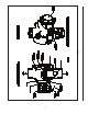
6. With the Model B Manual Emergency Station, valve D (Fig. 6), open, push in and rotate the Deluge Valve’s external reset knob (#14, Fig. 5) clockwise until you hear a distinct clicking noise, indicating that the clapper has closed. Note: The reset knob can be rotated only after pressure in the pushrod chamber is reduced to atmospheric conditions (0 psig). 7. Inspect and replace any portion of the sprinkler system subjected to fire conditions. 8. Open valve A (Fig.
. Fig.
Models DDX 2” (50mm), 2½” (65mm) 3” (80mm) & 76mm Deluge Valve Parts List Part Number Item No. 2” Valve 21/2” Valve 3” Valve 76mm 1 91006011 91006012 91006013 91006023 Body, Machined 1 2 94617001 94617002 94617003 94617004 Part Description No.
Fig. 6 14.
Maintenance Procedures - Model DDX Deluge Valve At the rear of the valve, disconnect the water column drain trim section starting with the elbow connector (#16, Fig. 2). Then remove the ¼” angle valve (#61, Fig. 2), followed by the ¾” x ¼” reducing bushing (#7, Fig.2). Remove the retaining ring (handhold cover side) from the clapper hinge pin (#30, Fig. 5) and push this pin through the water column drain line and remove the clapper subassembly. Replace the seal sub-assembly as described previously.
a. Shut down the valve controlling water supply to the Deluge Valve. Relieve the inlet pressure by opening the 1¼” drain valve B (Fig. 6). Close the valve A (Fig. 6) that supplies water to the push rod chamber, and open the Model B Manual Emergency Station, valve D (Fig. 6). b. Remove the trim at the unions nearest to the push rod chamber cover (#3, Fig. 5). c. Take the push rod chamber cover (#3, Fig. 5) off by removing the six retaining screws (#26, Fig. 5).
Ordering Information Specify • Valve Model & Size — 2” (50mm) Model DDX Deluge Valve (P/N 6103022000), 2½” (65mm) Model DDX Deluge Valve (P/N 6103022500), 3” (80mm) Model DDX Deluge Valve (P/N 6103030000), 76mm Model DDX Deluge Valve (P/N 6103027600). • Trim — The trim set is available in individual parts, in time-saving segmentally assembled kit forms, or fully assembled to the Model DDX Deluge Valve with or without a control valve. • Solenoid valve — 175 psi (12,1 bar) or 250 psi (17,2 bar) rated.
. Fig.
Installation Dimensions in Inches (mm) VALVE A B C *D E F G H J K L M N P Q R 2” (50mm) 2½” (65mm) 3” (80mm) & 76mm 73/4” (197) 61/4” (159) 8 (203) 121/2” (318) 181/2” (470) 261/4” (667) 51/2” (140) 91/4” (235) 3½ (89) 51/4” (134) 93/4” (248) 21/4” (57) 33/4” (95) 53/4” (146) 81/4” (210) 31/4” (83) * Total take out dimension for Fully Assembled to DDX Valve w/Control Valve Configurations: 2” - 207/32, 21/2” & 3” - 1727/32””, 76 mm - N/A. 19.
SOLENOID VALVE INSPECTIONS, TESTS AND MAINTENANCE WARNING: THE OWNER IS RESPONSIBLE FOR MAINTAINING THE FIRE PROTECTION SYSTEM IN PROPER OPERATING CONDITION. ANY SYSTEM MAINTENANCE OR TESTING THAT INVOLVES PLACING A CONTROL VALVE OR DETECTION SYSTEM OUT OT SERVICE MAY ELIMINATE THE FIRE PROTECTION OF THAT SYSTEM. PRIOR TO PROCEEDING, NOTIFY ALL AUTHORITIES HAVING JURISDICTION. CONSIDERATION SHOULD BE GIVEN TO EMPLOYMENT OF A FIRE PATROL IN THE AFFECTED AREA.