
Operator`s manual

Q-DL-2100 Operatorʼs Manual
Quaesta Instruments, LLC (520) 449-3806 • Email: support@quaestainstruments.com
8
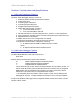
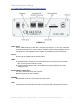
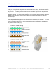
1.5 Q-DL-2100 Datalogger Back Panel Layout
FIGURE 1-2
RJ-45 Connectors are utilized for the Analog Out, Analog In, Digital I/O and Sensor
subsystems as well as for Relays and RS-232 interfaces:
Standard Ethernet cable and connectors may be used.
Regulated 5V Output:
1.0 X 4.2MM barrel type power jack. The 5V regulated output may be turned ON/OFF
via the appropriate datalogger INI parameter.
Regulated 12V Output:
1.3 X 4.2MM barrel type power jack. Note that 12.3V DC or greater must be supplied
to the datalogger Power input to enable the full 12V regulated power output. The 12V
regulated output may be turned ON/OFF via the appropriate datalogger INI parameter.
Iridium Satellite Modem Antenna Connection:
- For dataloggers with an integrated Iridium satellite modem, a standard SMA female
connector is present for connecting a user supplied Iridium antenna. Quaesta Instruments
can provide the antenna and cable or suggest an appropriate supplier. Contact Quaesta
Instruments for pricing and details.
Barometer:
-An integrated barometer is present. A hose barb allows for pressure monitoring at
some distance from the datalogger.