
Operator`s manual

Q-DL-2100 Operatorʼs Manual
Quaesta Instruments, LLC (520) 449-3806 • Email: support@quaestainstruments.com
7
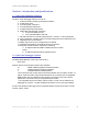
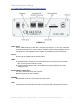
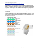
1.4 Q-DL-2100 Datalogger Front Panel Layout
FIGURE 1-1
Power Input:
2.5 X 5.7MM barrel type power jack. Nominal 12V required. 6 - 26 V DC is allowed.
A voltage greater than 12.3 VDC must be utilized to enable a fully regulated 12V DC
output (5V and 12V regulated power outputs are available from the back panel).
On/Off :
Power may be toggled with the On/Off Switch
LEDs:
P: Heartbeat LED. Flashes at a nominal cadence of once every 8 seconds while
idle, once every second while not idle.
Q: Data Acquistion indicator LED. Illuminates during data acquisition and data
storage process.
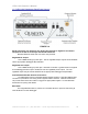
RJ-45 Interface Connectors:
Two jacks, labeled A and B, are provided.
Standard RJ-45 jacks are employed.
SD/MMC:
Standard SD card slot, Push In/Push Out type socket.
Com:
Terminal type Communication via USB is supported (with appropriate PC drivers)