Q-DL-2100 Data Logger Platform OPERATORʼS MANUAL Version: OM_9-2010, Rev B Quaesta Instruments, LLC 1665 E. 18th St., Ste 113 Tucson, AZ 85719 Telephone: (520)449-3806 E-mail: info@quaestainstruments.com Website: www.quaestainstruments.
Q-DL-2100 Operatorʼs Manual Customer Support QUAESTA INSTRUMENTS, LLC CUSTOMER SUPPORT PHONE: (520) 449-3806 INTERNET: www.quaestainstruments.com support@quaestainstruments.com WRITE: Quaesta Instruments, LLC 1665 E. 18th St., Ste 113 Tucson, AZ 85719 Attn: Customer Support MANUAL REVISION INFORMATION: The document and version number is listed on the front page. Please make note of these numbers when contacting Quaesta Instruments for customer support.
Q-DL-2100 Operatorʼs Manual Table of Contents Section 1: Introduction and Specifications.............................................................4 1.1 Q-DL-2100 Datalogger Platform ..................................................................................4 1.2 Q-DL-2100 Datalogger Options ...................................................................................4 1.3 Q-DL-2100 Datalogger Specifications..........................................................................5 1.
Q-DL-2100 Operatorʼs Manual Section 1: Introduction and Specifications 1.1 Q-DL-2100 Datalogger Platform The Q-DL-2100 datalogger platform consists of: 1. a Microcontroller containing specialized firmware 2. a Real-Time Clock 3. an Analog Input subsystem 4. an Analog Output subsystem 5. a Digital Input/Output subsystem 6. Redundant Data Storage, containing a. a user-removable SD card b. a non-removable Micro SD card 7. RS-232 interfaces for communicating with PCʼs, sensors, or other equipment 8.
Q-DL-2100 Operatorʼs Manual 1.3 Q-DL-2100 Datalogger Specifications • • Microcontroller based. • Program Execution Rate: o 1 min to 1 yr, in 1 minute increments. Analog Inputs: o 4 Single-Ended inputs. o 0 to 5V range. o 2.5 µ V resolution (21 bits) • • • • • • • • • • • o Integrated 50Hz or 60Hz noise suppression (Factory settable) o Conversion time for single channel measurement: • ~130 ms for 60 Hz suppression • ~150 ms for 50 Hz suppression o Aggregrate Attainable ADC Data Rate: • 5 Hz.
Q-DL-2100 Operatorʼs Manual Q-DL-2100 Datalogger Specifications, cont. • • • • • Power Requirements o Voltage: 6 to 26 V DC Note: Voltage greater than 12.3 V required to use fully regulated 12V output. o Typical Current Drain: Idle Mode: ~ 10 mA Note: 7 mA is quiescent current of Integrated pressure sensor. Can be powered from 12V or 24V solar panels. Datalogger Configuration o Via simple to use QILogger.ini text file on external SD card.
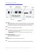
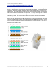
Q-DL-2100 Operatorʼs Manual 1.4 Q-DL-2100 Datalogger Front Panel Layout FIGURE 1-1 Power Input: 2.5 X 5.7MM barrel type power jack. Nominal 12V required. 6 - 26 V DC is allowed. A voltage greater than 12.3 VDC must be utilized to enable a fully regulated 12V DC output (5V and 12V regulated power outputs are available from the back panel). On/Off : Power may be toggled with the On/Off Switch LEDs: P: Heartbeat LED.
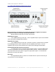
Q-DL-2100 Operatorʼs Manual 1.5 Q-DL-2100 Datalogger Back Panel Layout FIGURE 1-2 RJ-45 Connectors are utilized for the Analog Out, Analog In, Digital I/O and Sensor subsystems as well as for Relays and RS-232 interfaces: Standard Ethernet cable and connectors may be used. Regulated 5V Output: 1.0 X 4.2MM barrel type power jack. The 5V regulated output may be turned ON/OFF via the appropriate datalogger INI parameter. Regulated 12V Output: 1.3 X 4.2MM barrel type power jack. Note that 12.
Q-DL-2100 Operatorʼs Manual 1.6 Q-DL-2100 Electrical Connections: Back Panel RJ45 modular 8 pin, 8 conductor Jacks are located on the Back Panel for the Analog Out, Analog In, and Digital I/O subsystems as well as the Sensors, Relays, and RS-232 interface connectors. Standard ethernet patch cable with an RJ45 modular 8 pin, 8 conductor Plug may be used. The cable jacket and individual wire insulation may be easily stripped at the other end to facilitate connections to other equipment.
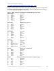
Q-DL-2100 Operatorʼs Manual 1.6 Q-DL-2100 Electrical Connections: Back Panel, cont. Below is a table of pinouts for the RJ45 connectors on the back panel and the corresponding wire colors for an EIA/TIA 568B type patch cable. Appropriate changes should be made if an EIA/TIA 568A type patch cable is used instead. Table 1.1 RJ45 Connector wiring diagram for EIA/TIA 568B type patch cable.
Q-DL-2100 Operatorʼs Manual Section 2: Datalogger Operation 2.1 Installation To install the Q-DL-2100 datalogger unpack the datalogger and follow these steps. 1. Configure the QILogger.ini located on the external SD card as appropriate and as described in detail in Section 2.2 below. This file can be edited via a simple word processor such as Wordpad or Notepad on a Microsoft Windows based PC. 2. Provide power to the datalogger via the Power Jack on the front panel.
Q-DL-2100 Operatorʼs Manual 2.3 INI Parameters Description Q-DL-2100 INI file parameters (Not Case Sensitive) Name= ? Extension= ? - Name of the Logger: e.g. 'name= QILogger'(16 max) - Extension of the filename: e.g. 'extension= 005'(3 chars max) *The extension of the data filenames written to the SD media // Data Acq Params StartTime= ? - Time to start logging (YYYY/MM/DD HH:MM:SS); e.g. 'starttime= 2009/07/04 14:30:00 StopTime= ? - Time to stop logging (YYYY/MM/DD HH:MM:SS); e.g.
Q-DL-2100 Operatorʼs Manual // Power Conservation Configuration // -----These params are active only if Battery Thresholding // -----is On or Daily Power Conservation is On Conserve5VPwr= ? Conserve12VPwr= ? ConserveNPMPwr= ? - Turns OFF/ON 5V Regulated Power Conservation, 0 or 1 - Turns OFF/ON 12V Regulated Power Conservation, 0 or 1 - Turns OFF/ON NPM Power Conservation, 0 or 1 // Battery Thresholding BatteryThresholdsOn= ? LowBatteryThresh= ?.
Q-DL-2100 Operatorʼs Manual 2.4 Sample QILogger.ini file The QILogger.ini file located on the external SD card may be edited directly via Wordpad or Notepad or other suitable text editor. Care should be taken to maintain the parameterʼs spelling. An equal sign or a space, or a combination of spaces and equal signs, between the parameter and its desired value are acceptable. Below is an example of a QILogger.ini file.
Q-DL-2100 Operatorʼs Manual 2.4 Sample QILogger.ini file, cont. // Daily Power Up and Down Times - see ConservePwrXXX params above DailyPwrConserveOn=0 DailyPwrUpHHMM=0600 DailyPwrDownHHMM=2000 // Remote Communications UseRS232=1 RS232BaudRate=19200 UseSatModem=0 -------------------------------------------------------------------------- The above QILogger.
Q-DL-2100 Operatorʼs Manual 2.4 Sample QILogger.ini file, cont //Digital I/O Configuration Dio1=1 Dio2=1 Dio3=3 Dio4=2 Digital I/O channels 1 and 2 are configured as counters while channels 3 and 4 are configured as a Digital Output and a Digital Input, respectively. // Neutron Pulse Module Configuration NumberOfNPMs=2 The number of Neutron Pulse Modules present in the Probe is set to 2. The current version of the datalogger firmware supports from 0 to 4 Neutron Pulse Modules.
Q-DL-2100 Operatorʼs Manual // Battery Thresholding BatteryThresholdsOn=1 LowBatteryThresh=11.5 ChargedBatteryThresh=12.6 Battery Thresholding is ON, so Power Conservation mode will be entered when the dataloggerʼs power supply voltage drops below 11.5 V. Likewise, after Power Conservation mode is entered, Power Conservation mode will only be exited when a power supply voltage greater than 12.6 V is obtained.
Q-DL-2100 Operatorʼs Manual 2.6 Terminal Interface Command Set When utilizing a terminal interface program to communicate with the datalogger, one can type ʻmenuʼ to see a list of both the available commands and the available INI parameters. i.e., in HyperTerminal window or Tera Term Pro terminal interface window, type ʻmenuʼ Result: menu ***List of available Commands (Not Case Sensitive)*** Test - Confirms Logger operation. Returns 'OK it works!'.
Q-DL-2100 Operatorʼs Manual DAC?= ?? * ?.??? - Map Dac? value, e.g. 'Dac3= T1 * 0.1'. Active only if DACMappingOn=1. Relays= ? - Which of 4 Relays activated: e.g.
Q-DL-2100 Operatorʼs Manual 2.7 Remote Communication Using Integrated Iridium Satellite modem. Description to be added soon. Using Integrated Cell Phone modem. Description to be added soon. Using External Teltonika WirelessCOM/ G10 GSM modem. The Teltonika WirelessCOM/G10 GSM modem allows one to connect to the datalogger from a remote location via an IP address.
Q-DL-2100 Operatorʼs Manual Appendix A: USB Communication Interface Setup Setting up the Q-DL-2100 USB Communication interface is easy and straightforward. Summary: 1. Obtain the appropriate USB Virtual COM Port Driver .zip file for your PC operating system. 2. Install the Virtual COM Port Driver. 3. Determine USB Virtual COM Port setting Detailed Instructions: Step 1. Obtain the appropriate USB Virtual COM Port Driver .zip file for your PC operating system.
Q-DL-2100 Operatorʼs Manual Figure A-1 Step 2. Install the Virtual COM Port Driver. For convenience a concise and brief guide for installation of the USB Virtual COM Port driver utilizing the Windows XP Found New Hardware Wizard is contained below. Thorough installation guides for Windows XP , Windows 2000, Windows 98, Windows ME, and Mac OSX platforms are also available at the FTDI website at http://www.ftdichip.com/Drivers/VCP.htm .
Q-DL-2100 Operatorʼs Manual When using Windows XP, the Found New Hardware Wizard should activate and display a window as shown below in Figure A-2. Figure A-2. To the question “Can Windows connect to Windows Update to search for software?” Select the “No, not this time” option as shown, and click Next. The window shown in Figure A-3 should be displayed. Figure A-3 Quaesta Instruments, LLC (520) 449-3806 • Email: support@quaestainstruments.
Q-DL-2100 Operatorʼs Manual Select “Install from a list or specific location (Advanced), and click Next. The Window shown below in Figure A-4 should appear. Figure A-4 Select the option button “Search for the best driver in these locations”. Then clear the checkbox “Search removable media (floppy, CD-ROM…)” and select the “Include this location in the search” checkbox. Use the Browse button to select the folder where the USB FTDI drivers were extracted in Step 1 above, and then click Next.
Q-DL-2100 Operatorʼs Manual STEP 3. Determine USB Virtual COM Port setting. After Step 2 is complete, the USB Virtual COM Port should be installed. This will make the USB connection to the data logger behave as a Windows serial port, otherwise known as a COM port. To verify this, leave the USB port on the PC connected to the COM connector on the data logger. Now go to the Windows Control Panel (accessible from the Start Menu).
Q-DL-2100 Operatorʼs Manual Select System to open up the System Properties window, shown in Figure A-7. Figure A-7 Select the Hardware tab to reveal a window of the form shown in Figure A-8. Figure A-8 Quaesta Instruments, LLC (520) 449-3806 • Email: support@quaestainstruments.
Q-DL-2100 Operatorʼs Manual Select Device Manager and look for an entry under Ports (COM & LPT) which corresponds to the USB Virtual COM Serial Port. It will look like any other COM port, but will generally be assigned a number higher than 2. i.e., COM3 in Figure A-9 below. Figure A-9 If multiple serial ports show up, simply unplug the USB cable from the COM port on the QDL-2100 data logger and identify which COM port number disappears. It should reappear when the USB cable is plugged in again.
Q-DL-2100 Operatorʼs Manual Appendix B: Terminal Emulation Software Setup There are a variety of terminal emulation software programs capable of communicating through the PCʼs COM ports to the Q-DL-2100 datalogger. Quaesta Instruments has utilized both the standard Windows HyperTerminal communication application included with Windows as well as a freely available application called Tera Term Pro.
Q-DL-2100 Operatorʼs Manual B.1 Windows HyperTerminal Communications Setup Open the Windows HyperTerminal application (accessible from Start->All Programs>Accessories->Communications->HyperTerminal). Upon first use of HyperTerminal, a “Location Information” window of the form shown in Figure B-1 will appear. Figure B-1. Simply enter anything in the area code box and click OK (this screen is not relevant for our work as we will not be using a modem).
Q-DL-2100 Operatorʼs Manual You will be presented with a “Connection Description” window of the form shown in Figure B-2. Figure B-2. Enter a name for the connection and click OK. At the “Connect To” window, shown in Figure B-3, select the appropriate COM Port (determined in Appendix A, Step 3 if using the dataloggerʼs USB COM port) from the “Connect using: ” pull-down list. Figure B-3. Select OK and a window similar to Figure B-4 will be displayed.
Q-DL-2100 Operatorʼs Manual Figure B-4. Click Apply and then OK. For use as a terminal interface, the user will find it useful to further configure the Hyperterminal display. Setting the Font To change the Font select View-> Font… from the main menu to display the Font configuration Window as shown in Figure B-5. A Font Size of 9 works well. Figure B-5. Quaesta Instruments, LLC (520) 449-3806 • Email: support@quaestainstruments.
Q-DL-2100 Operatorʼs Manual Setting the Terminal Emulation Select File->Properties and then select the Settings tab. Select VT100 for Emulation. Make sure the “Backscroll buffer lines” parameter is set to 500, the maximum number. Figure B-6. Setting the Terminal Properties Select the “Terminal Setup…” button in the Connection Properties window (displayed in Figure B-7. A window titled “Terminal Settings” will be displayed. Configure it for 132 column mode as below.
Q-DL-2100 Operatorʼs Manual Saving the HyperTerminal Configuration To Save a configuration for rapid recall, select File->Save or Save As… as appropriate to save the current Hyperterminal configuration. When starting Hyperterminal (after the first use) one will see the “Connection Description” window shown in Figure B-8. Opening or Recalling a Saved Hyperterminal Configuration Upon starting up Hyperterminal the window in Figure B-8 may be displayed.
Q-DL-2100 Operatorʼs Manual B.2 TeraTerm Pro Communications Setup Tera Term Pro is an open source free software terminal emulator (terminal communication application) for MS-Windows. It provides for a very convenient means of communicating with the Quaesta Instrument Q-DL-2100 datalogger, and its displayed output can be more easily configured than Windows Hyperterminal. An alternative is the Windows Hyperterminal program if using Windows 2000 or Windows XP.
Q-DL-2100 Operatorʼs Manual Figure B-11. Step 4. Configuring the Terminal. Select Setup->Terminal… from the main menu. Configure as in Figure B-12. Figure B-12. Step 5. Configuring the Terminal Display Window. Select Setup->Window… from the main menu. Configure as in Figure B-13. Figure B-13. Quaesta Instruments, LLC (520) 449-3806 • Email: support@quaestainstruments.
Q-DL-2100 Operatorʼs Manual Step 6. Configuring the Serial Port parameters. Select Setup->Serial Port from the main menu. a. b. If using the dataloggerʼs USB COM port, configure the parameters as in Figure B-14. *Note that the Port number selected must match the dataloggerʼs USB Virtual Serial port number as found in Appendix A, Step 3.
Q-DL-2100 Operatorʼs Manual Appendix C: Upgrading the Q-DL-2100 Firmware The Q-DL-2100 datalogger firmware includes a bootloader program which allows for user upgrades of the firmware in the field (if necessary). To upgrade the firmware on the Q-DL-2100 datalogger the user should follow the steps below: 1. Obtain the latest QDL2100.bin firmware from Quaesta Instruments personnel. Please contact Quaesta Instruments via email at support@quaestainstruments.