
DTU DL100EU User Manual--ShowDoc

2022/4/2 15:49
DL100EU DTU User Manual--ShowDoc
doc.rejeee.com/web/#/32?page_id=353
5/5
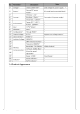
DL100EU LoRa DTU definition as below
The standard DTU supports one RS-485 interface and is connected with two core cables, namely “rs485a” line
and “rs485b” line. It can also be converted into RS232 interface or other interfaces through the external serial
port conversion module.
The power input can be powered directly by the adapter with 2.5mm DC round head plug or through the wiring
terminal, one of which can be selected.
The connector adopts plug-in wiring terminal. The signal line or power line adopts the terminal plug, and the
signal lead is fixed with a cross screwdriver and directly inserted into the corresponding terminal socket of DTU.
You can configue frequency, TX power, bandwitch etc through sensor tool, and configuration tool as below:
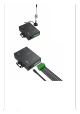
When get DL100EU DTU, you only need to fix the peripheral small ear hole on the installation object. If it does
not need to be fixed, it can be placed horizontally.
Note: the angle of the antenna should be considered when installing the terminal. In order to ensure the signal
quality between the terminal and the receiving point, it is recommended to avoid metal shielding within a certain
distance in the direction of the antenna radiation field during installation.
2.4.Wiring Instructions
2.5.Configuration Instructions
3. Installation
3.1.DL100EU LoRa DTU Installation