
User`s guide

13800-101-Rev. A 5
Z
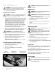
Alignment
You can choose an optimum projection distance when
patient and projector are equally away from the
projection screen.
Images can be optimally focused at projection distances
between 10 ft. (3 m ) and 26.5 ft. (8 m ).
1. Project a 20/200 or 0.1
"
Z
"
(or other characters) onto
the screen by pressing the key.
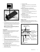
2. Check the three dimensional alignment of the system.
The projector is optimized when the projection
screen is angled to direct light to the patients head.
Place a mirror on the screen. The light should project
where the patient's head would be (see Figure 4,
below).
3. Adjust the image positioning on the screen. It may be
necessary to adjust the projector and the screen.
Secure projector by tightening mounting screw .
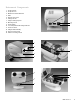
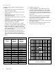
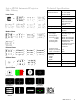
4. Determine the proper letter size based on the
refracting distance used. Refer to Figure 3, below,
and the Letter Sizing Charts at the end of this manual
(see Figures 9 & 10, pp. 10 - 11).
5. Attach Letter Sizing Chart to the screen.
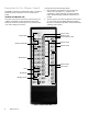
6. Open the unit's projector head cover by lossening the hexagon
screw located on the bottom side of the projector head (see
Instrument Components, p.3, #6).
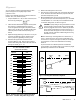
6. Move the AP250's Chart Focusing Control and Distance
Focusing Control (see "Instrument Components, p. 3, #13 & #14)
until the 20/200 or .01 "Z" is in sharp focus and fills the bracket
on the Letter Sizing Chart, as shown in Figure 3.
CAUTION: Properly setting focusing and distance controls
requires that the projector head cover be opened while
the unit is plugged in and turned on. Utilize only the Chart
Focus Control and the Distance Focusing Control (p. 3, #
13 & #14) to obtain the proper focus. Do not touch any of
the other internal components while setting the focusing
and distance controls.
Note: To obtain longer refracting distances in small rooms, a
mirror or system of mirrors can be used. A high quality front
surface mirror is required. See Figure 5, below, as an example
of arrangement of a short room with full 20 foot refracting
distance.
To prevent interference with the operation of the Remote
Control window, care should be taken not to position any bright
lights directly toward the front of the AP250.
Figure 3 - Reduced-sized version of Letter Sizing Chart
(not to scale -- see Letter Sizing Charts on pp. 10-11).
Figure 4 - Checking three dimensional alignment.
Figure 5 - Using a mirror system in a small room.
8.53
7.92
7.32
6.71
6.10
5.49
4.88
4.27
3.66
3.05
2.44
30
28
26
24
22
20
18
16
14
12
10
8
29
27
25
23
21
19
17
15
13
11
9
7
8.83
8.23
7.62
7.01
6.40
5.79
5.18
4.57
3.96
3.35
2.74
2.14
METERS
FEET
REFRACTING DISTANCE
LETTER SIZING CHART
➠
➠
AP250
Screen
Patient
Spot of
Light on
Wall
Screen
Patient
AP250
Small
Mirror
Patient
Mirror
Mirror
9.14