
Product Manual


10
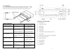
RADIO REMOVAL
3. To remove the radio, disconnect the rear support stud if installed. Carefully
release the front Trim Ring lock tabs at the top and bottom of the nosepiece. Then
insert the two release keys on both sides of the nosepiece and pull the radio out.
TROUBLESHOOTING
Problem Cause Measure
Power light does not turn on No power to yellow wire; no power
to red wire; blown fuse
Check for ACC/BATTERY
voltage with Multi-meter, check
fuse; press RESET button.
No sound Speakers not connected; speakers
connected with bad splices;
Speakers shorted to ground; total
speakers load not within 4-8/ch
Connect speakers to harness;
check all spliced wires; verify
speakers not shorted to chassis;
verify total speaker impedance.
Public Address can NOT be
heard over speakers
Microphone volume level is “0”;
microphone is plugged into the
wrong input; wrong microphone
type is used
Turn the volume up when the
LCD display’s MIC 1 or MIC 2;
Check that the correct
microphone type is connected
Digital media won’t play or
says “ERROR” and skips to
“AUX”
Media is an unsupported file type. Encode media with a supported
file type; make sure disc has
been finalized; use different
software
Disc errors during CD playback Disc is scratched, internal optics
dirty, or the angle of operation is
too extreme.
Restore the CD by removing the
scratches. Adjust the angle of
operation to between 0°-30°.
LCD Display says MIC /MIC 1/
or MIC 2 and front controls are
locked
PA system is triggered Remove microphone connections
and verify correct pinning;
replace microphone
3
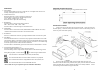
CONTROLS AND INDICATORS
(1) Power Button
(2) Volume/Select Knob
(3) Band Button
(4) Mode Button
(5) Reset Button
(6) Scan Button
(7) Preset Memory Buttons/r Playback Options
(8) Mute Button
(9) Radio Station Tune/Seek, Track Control Buttons
(10) Front Auxiliary Input Jack
(11) SD Card Input slot
(12) Display Button
(13) Clock Button
(14) USB Input Slot
(15) Eject Button