
Owner's Manual
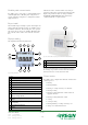
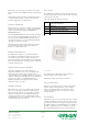
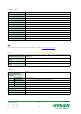
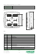
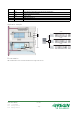
Table Of Contents
- Application
- Function
- Sensor
- Actuators
- Flexibility with communication
- Easy to install
- Display handling
- Control modes
- Operating modes
- Occupancy detector
- The occupancy button
- Forced ventilation
- Change-over function
- Control of electrical heater
- Setpoint adjustment
- Built-in safety functions
- Supply air temperature limitation
- Actuator exercise
- Fan control
- Fan boost function
- Fan kickstart
- Relay module, RB3
- Configuration and supervision using Application Tool
- Technical data
- Inputs
- Outputs
- Setpoint settings via Application Tool or in display
- Dimensions
- Wiring
- Application examples
- Documentation

Setpoint settings via Application Tool or in display
Basic heating setpoint 5...40°C
Basic cooling setpoint 5...50°C
Setpoint displacement ±0...10°C (FI=±3°C)
Dimensions
60
68
28
95
[mm]
Wiring
Terminal Designation Function
10 G Supply voltage 24 V AC
11 G0 Supply voltage 0 V
12 DO1 Output for fan control I
13 DO2 Output for fan control II
14 DO3 Output for fan control III
20 GDO 24 V AC out common for DO
21 G0 0 V common for UO (if using 0...10 V actuators)
22 DO4 Output for forced ventilation
23 UO1 Output for 0...10 V valve actuator alt. thermal or On/Off actuator. Heating (FS) Cooling or Heating or
Cooling via change-over.
24 UO2 Output for 0...10 V valve actuator alt. thermal or On/Off actuator. Heating, Cooling (FS) or Heating or
Cooling via change-over
30 AI1 Input for an external setpoint device, alt. supply air temperature limitation sensor
31 UI1 Input for change-over sensor, alt. potential-free contact
HEAD OFFICE SWEDEN
Phone: +46 31 720 02 00
Web: www.regincontrols.com
E-mail: info@regincontrols.com
RC-CDFO
— 7 (8) —