www.regency-fire.com U41 Gas Insert Owners & Installation Manual MODELS: U41-NG3 Natural Gas U41-LP3 Propane WARNING: If the information in these instructions are not followed exactly, a fire or explosion may result causing property damage, personal injury or loss of life. FOR YOUR SAFETY What to do if you smell gas: Do not try to light any appliance Do not touch any electrical switch: do not use any phone in your buildFOR YOUR SAFETY ing.
REGENCY GAS FIREPLACE INSERT TO THE NEW OWNER Congratulations! You are the owner of a state-of-the-art Gas Insert by FIREPLACE PRODUCTS INTERNATIONAL LTD. The Regency ULTIMATE Gas Fireplace Series of hand crafted appliances has been designed to provide you with all the warmth and charm of a fireplace, at the flick of a switch. The models U41-NG3 and U41-LP3 of this series have been approved by Warnock Hersey for both safety and efficiency.
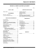
TABLE OF CONTENTS REGENCY ULTIMATE GAS FIREPLACE INSERT Page SAFETY LABEL Safety Labels ................................................... 4 REQUIREMENTS MA Code - CO Detector (for state of Massachusetts only) ......................... 5 INSTALLATION REQUIREMENTS For your safety ................................................. 6 Gas Pipe Testing .............................................. 6 Specifications ...................................................
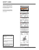
SAFETY LABEL This is a copy of the label that accompanies each Regency ULTIMATE Gas Insert. We have printed a copy of the contents here for your review. The safety label is located on the right side door panel. NOTE: Regency units are constantly being improved. Check the label on the unit and if there is a difference, the label on the unit is the correct one. Duplicate Serial No. 225 DO NOT REMOVE THIS LABEL Serial No.
REQUIREMENTS MA Code - CO Detector (for the State of Massachusetts only) 5.08: Modifications to NFPA-54, Chapter 10 (2) Revise 10.8.
INSTALLATION IMPORTANT: SAVE THESE INSTRUCTIONS The Regency Gas Fireplace must be installed in accordance with these instructions. Carefully read all the instructions in this manual first. Consult the building authority having jurisdiction to determine the need for a permit prior to starting the installation. Note: Failure to follow these instructions could cause a malfunction of the heater which could result in death, serious bodily injury, and/or property damage.
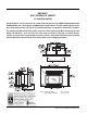
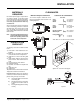
INSTALLATION MATERIALS REQUIRED No electrical power supply is required for the gas control to operate. A 120 Volt AC power cord is hooked up to the fan switch and blower. Plug 3 wire cord into a suitable receptacle. Do not cut the ground terminal off under any circumstances. CLEARANCES Clearances to Combustibles Minimum Fireplace Clearances The minimum fireplace clearances for the Regency gas fireplace insert are shown in the following diagrams: Sides Ceiling Mantel From Unit A 7.
INSTALLATION Combustible Mantel Clearances Depth (Mx) 5-1/2" 6" 6-1/2" 7" 7-1/2" 8" 8-1/2" 9" 9-1/2" Clearance (My) 11" 11-3/8" 11-3/4" 12-1/4" 12-1/2" 12-5/8" 12-3/4" 12-7/8" 13" Non-combustible Hearth Extension Height (Hy) 0" 5/8" 1-1/4" 1-7/8" 2-3/8" 2-3/4" 3-1/8" 3-1/2" 3-3/4" 4" Depth (Hx) 25" 24" 23" 22" 21" 20" 19" 18" 17" 16" Note: A non-combustible mantel may be installed at a lower height if the framing is made of metal studs covered with a non-combustibl
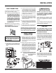
INSTALLATION GAS CONNECTION For minimum and maximum supply pressure see the System Data table on page 7. Note: Prior to any pressure testing of the gas supply piping system that exceeds test pressures of 1/2 psig, this appliance and its individual shut-off valve must be disconnected from the piping system. If test pressures equal to or less than 1/2 psig are used then this appliance must be isolated from the piping system by closing its individual manual shut-off valve during the testing.
INSTALLATION The Regency Insert incorporates its own internal draft hood, so no additional external draft hood is required. Periodically check that the vent is unrestricted and an adequate draft is present when the unit is in operation. (See page 9 for spillage test.) Natural Gas: Propane: 3/16" open 1/2" open The aeration adjustment gears are located on the right side of the burner box and can be accessed from the side or from the front when the louvers are removed.
INSTALLATION shut off the supply of gas within 5 - 10 minutes. Tampering with the switch can result in carbon monoxide (CO) poisoning and possible death. If the heater turns off because of lack of draft during the spillage test, check for the cause and if necessary, seek expert advice. The thermally actuated safety switch will automatically reset after it has reduced in temperature. The switch will continue to cycle until the draft problem is corrected. DO NOT BYPASS OR DISCONNECT THIS SWITCH.
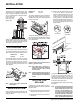
INSTALLATION LOG INSTALLATION WARNING: Dangerous operating conditions may occur if these logs are not positioned in their approved locations. Read the instructions below carefully and refer to the diagrams. If logs are broken do not use the unit until they are replaced. Broken logs can interfere with the pilot and burner operation.
INSTALLATION OPTIONAL WALL THERMOSTAT OPTIONAL REMOTE CONTROL A wall thermostat may be installed if desired. Connect the wires as per the wiring diagrams on page 13. Use table on this page to determine the maximum wire length: Use the Regency Remote Control Kit approved for this unit. Use of other systems may void your warranty. Note: Preferable if the thermostat is installed on an interior wall. The remote control kit comes with a hand held transmitter, a receiver and a wall mounting plate.
INSTALLATION WIRING DIAGRAM This heater does not require a 120V A.C. supply for operation. In case of a power failure, the burner switch and the optional remote control/ thermostat will continue to operate. However, a 120V A.C. power supply is needed for the fan/blower operation. Caution: Ensure that the wires do not touch any hot surfaces and are away from sharp edges. CAUTION: Label all wires prior to disconnection when servicing controls.
OPERATING INSTRUCTIONS OPERATING INSTRUCTIONS Before operating this appliance, proceed through the following check list. 5) Wait five minutes to allow gas, that may have accumulated in the main burner compartment, to escape. If you do smell gas, follow the instructions on the front of this manual. If you don't smell gas continue on to the next step. 1) Read and understand these Instructions before operating this appliance. 6) Turn the gas control counterclockwise to "PILOT".
OPERATING INSTRUCTIONS COPY OF THE LIGHTING PLATE INSTRUCTIONS FOR YOUR SAFETY READ BEFORE LIGHTING This appliance must be installed in accordance with local codes, if any; if not, follow the current CAN1-B149/ANSI Z 223.1 (Australia: AG601 / New Zealand: NZS 5261) WARNING: If you do not follow these instructions exactly, a fire or explosion may result causing property damage, personal injury or loss of life.
MAINTENANCE NORMAL OPERATING SOUNDS OF GAS APPLIANCES It is possible that you will hear some sounds from your gas appliance. This is perfectly normal due to the fact that there are various gauges and types of steel used within your appliance. Listed below are some examples. All are normal operating sounds and should not be considered as defects in your appliance. Blower: Regency gas appliances use high tech blowers to push heated air farther into the room.
MAINTENANCE LOG REPLACEMENT MITRED DOOR The unit should never be used with broken logs. Turn off the gas valve and allow the unit to cool before opening door to carefully remove the logs. The pilot light generates enough heat to burn someone. If for any reason a log should need replacement, you must use the proper replacement log. The position of these logs must be as shown in the diagram under Log Installation.
MAINTENANCE FAN MAINTENANCE If your fan requires maintenance or replacement, access to the fan is through the access panel on the rear wall of the firebox. NOTE: the unit MUST NOT be operated without the fan access panel securely in place and correctly sealed.
PARTS LIST MAIN ASSEMBLY Part # Description 1) 2) 9) 10) 611-525 653-535/02 590-105 936-196 Bottom Louver Assy Top Louver Assy Fan Cover Fan Cover Gasket 23) 24) 25) 26) 11) 12) 610-517/P 910-157/P 910-794 910-770 Fan Assembly (120 V) Fan Motor Power Cord (120 V) Wire Harness (stove connection end) 27) 28) 30) 31) 19) 20) 21) 22) 613-520 650-527 613-522 650-528 Side Panel Assy - Left Side Panel Hinge Bracket - Left Side Panel Assy - Right Side Panel Hinge Bracket - Right 20 Part # Descriptio
PARTS LIST BURNER & LOGS 52) 56) 60) 71) 72) 75) 78) 80) 81) Part # Description 910-190 910-426 Piezo Ignitor and nut Knob - Flame Hi/Low Extension 613-524/P 613-526/P 910-028 910-029 904-688 904-641 Valve Assembly -NG Valve Assembly - LP Valve - RS - NG Valve - RS - LP Orifice - #32 NG Orifice - #50 LP * 910-034 910-035 653-930 653-531 260-565 904-565 Log Stand Pilot Hood Assy- 3 Flame NG Pilot Hood Assy- 3 Flame LP Log Set Burner Assy Air Shutter Gear Assembly (Female) Hex Key 3/16" A/F *Not ava
PARTS LIST FACEPLATE & TRIM Part # Description 611-930 Ultimate Factory Built Trim Kit 103) Faceplate & Trim - Complete - Oversize Faceplate - Oversize - Side Right Faceplate - Oversize - Top Assy Faceplate - Oversize - Side Left Assy Trim Pkg.
WARRANTY Regency Fireplace Products are designed with reliability and simplicity in mind. In addition, our internal Quality Assurance Team carefully inspects each unit thoroughly before it leaves our facility. FPI Fireplace Products International Ltd. is pleased to extend this limited lifetime warranty to the original purchaser of a FPI Product. This warranty is not transferable.
Regency fireplace products are designed with reliability and simplicity in mind. In addition, our internal Quality Assurance Team carefully inspects each unit thoroughly before it leaves our door. Fireplace Products International Ltd. is pleased to extend this Limited Lifetime Warranty to the original purchaser of a Regency Product. See the inside back cover for details. Register your Regency online at http://www.regency-fire.