www.regency-fire.com ULTIMATE U38 Freestanding Gas Stove MODELS: U38-NG1 Natural Gas Owners & Installation Manual U38-LP1 Propane FOR YOUR SAFETY WARNING: If the information in these instructions are not followed ex- What to do if you smell gas: Do not try to light any appliance actly, a fire or explosion may result causing property damage, Do not touch any electrical switch: personal injury or loss of life. do not use any phone in your buildFOR YOUR SAFETY ing.
To the New Owner: Congratulations! You are the owner of a state-of-the-art ULTIMATE Gas Stove by FIREPLACE PRODUCTS INTERNATIONAL LTD. The Regency® Gas Series of hand crafted appliances has been designed to provide you with all the warmth and charm of a woodstove, at the flick of a switch. The models U38-NG1, and U38-LP1 of this series has been approved by Warnock Hersey for both safety and efficiency.
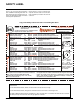
TABLE OF CONTENTS SAFETY LABEL OPERATING INSTRUCTIONS Serial No. Decal ............................................................4 Operating Instructions ................................................19 Lighting Instructions ....................................................19 Shutdown Instructions .................................................19 First Fire ......................................................................19 Automatic Convection Fan Operation .........................
SAFETY LABEL This is a copy of the label that accompanies each ULTIMATE Freestanding Gas Stove. We have printed a copy of the contents here for your review. The safety label is located on the inside of the drop down pedestal door. NOTE: Regency® units are constantly being improved. Check the label on the unit and if there is a difference, the label on the unit is the correct one.
REQUIREMENTS MA Code - CO Detector (for the State of Massachusetts only) 5.08: Modifications to NFPA-54, Chapter 10 (2) Revise 10.8.
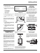
INSTALLATION BEFORE YOU START Safe installation and operation of this appliance requires common sense, however, we are required by the Canadian Safety Standards and ANSI Standards to make you aware of the following: INSTALLATION AND REPAIR SHOULD BE DONE BY A QUALIFIED SERVICE PERSON. THE APPLIANCE SHOULD BE INSPECTED BEFORE USE AND AT LEAST ANNUALLY BY A PROFESSIONAL SERVICE PERSON. MORE FREQUENT CLEANING MAY BE REQUIRED DUE TO EXCESSIVE LINT FROM CARPETING, BEDDING MATERIAL, ETC.
INSTALLATION 6) Test Gas Pressure. Refer to the "Gas Pipe Pressure Testing" section. 7) Install standard and optional features. Refer to the following sections where applicable. a. Log Set Installation b. Front Door Installation c. Louver Installation d. Wall Thermostat e.
Regency® U38-1 ULTIMATE Freestanding Gas Stove
INSTALLATION GAS CONNECTION The gas line can be rigid pipe, or to make installation easier, use a listed flexible connector if allowed by local codes. Copper may also be used if approved by local codes. The gas connection at the valve is 3/8" NPT. For minimum and maximum supply pressure see the System Data Table. System Data U38-1 with 40,000 BTU U38-NG1: For 0 to 2000 feet altitude U38-LP1: For 0 to 4500 feet alttitude Burner Inlet Orifice Sizes: Natural Gas Burner #31 Propane #50 Max.
INSTALLATION CONVERSION KIT# 731-969 FOR NG TO LP THIS CONVERSION MUST BE DONE BY A QUALIFIED GAS FITTER IF IN DOUBT DO NOT DO THIS CONVERSION !! 3) Remove burner. See diagram below. 9) Insert a 5/32” or 4mm Allen wrench into the hexagonal key-way of the screw (Fig. 2), rotate it counter-clockwise until it is free and extract it. Each Kit contains one LPG Conversion Kit and one DC Sparker Kit. LPG Conversion Kit Contains: Qty.
INSTALLATION WARNING! Do not over tighten the screw. Recommended to grip the wrench by the short side. 16) Unscrew the pilot orifice with the allen key and replace with the LPG pilot orifice in the kit. 23) Remove the front control panel by unscrewing the 6 screws. 13) Verify that if the conversion is from NG to LPG, the screw must be reassembled with the red o-ring visible (Fig. 5).
INSTALLATION 28) Secure with screw. 33) Attach the Piezo Ignition Wire to the back of the DC Sparker box. 37) Attach the green ground wire. green ground wire 29) Reversing step 23 and secure the control panel back onto the stove pedestal with the screws. 34) The ground wire and DC Sparker ignition go through the hole on the heat shield. 38) Install the supplied battery into the DC Sparker Box by opening the battery compartment. NOTE: The battery in the DC Sparker Box will need to be replaced annually.
INSTALLATION LOG SET INSTALLATION CONVERSION TO LOWER BTU RATING THIS CONVERSION MUST BE DONE BY A QUALIFIED GAS FITTER IF IN DOUBT DO NOT DO THIS CONVERSION !! Natural Gas Conversion Kit 730-920 Contains: Qty. Part # Description 1 904-240 Burner Orifice #37 (NG) 1 918-034 Decal "Converted to 30,000 Btu" 1 918-033 Instruction Sheet Propane Conversion Kit 730-922 Contains: Qty.
INSTALLATION 3) Place Rear Log A)02-65 on the two pins on the rear log support. 7) Place the Left Top Log D)02-46 on the pin on Log B)02-56 and on top of the cutout on Log A)02-65. 11) Position notch in Front Right Log G)02-48 on Log F)02-47 and push the bottom right edge against the bracket on the burner tray. G)02-48 A)02-65 A)02-65 A)02-65 F)02 -4 7 D)02-46 B)02-56 C)02-44 E)02-45 Pins on Rear Log Support 4) Place the Middle Left Log B)02-56 on the two pins as shown.
INSTALLATION FRONT DOOR INSTALLATION (packaged separately) 1) Open the two side panels. LOUVER INSTALLATION 1) Attach the top & bottom louvers to the side stove panel using 2 screws per side. The smoke should be drawn into the draft hood. If the smoke is not drawn into the draft hood, turn the unit off and check for the cause of lack of draft. . 2) Slide the door onto the two hinge pins making sure the two pieces are flush together. See diagram 1. 3) Close the door.
INSTALLATION FINAL CHECK OPTIONAL WALL THERMOSTAT OPTIONAL REMOTE CONTROL A wall thermostat may be installed if desired. Connect the wires as per the wiring diagrams. Note that the wires are connected to the "TH" on the gas valve. Use table below to determine the maximum wire length: Use the Regency® Remote Control Kit approved for this unit. Use of other systems may void your warranty. Note: Preferable if the thermostat is installed on an interior wall.
WIRING DIAGRAMS Regency® U38-1 ULTIMATE Freestanding Gas Stove 17
Regency® U38-1 ULTIMATE Freestanding Gas Stove
OPERATING INSTRUCTIONS OPERATING INSTRUCTIONS Before operating this appliance, proceed through the following check list. 1) Read and understand these Instructions before operating this appliance. 2) Check to see that all wiring is correct and enclosed to prevent possible shock. 3) Check to ensure there are no gas leaks. 4) Make sure the three pieces of door glass are properly positioned. Never operate the appliance with any of the glass removed or with the door open.
OPERATING INSTRUCTIONS COPY OF THE LIGHTING PLATE INSTRUCTIONS FOR YOUR SAFETY READ BEFORE LIGHTING This appliance must be installed in accordance with local codes, if any; if none, follow the National Fuel Gas Code, ANSI Z223.1/ NFPA 54, or Natural Gas and Propane Installation Codes, CSA B149.1. (Australia: AS5601-2004, New Zealand: NZS 5261) WARNING: If you do not follow these instructions exactly, a fire or explosion may result causing property damage, personal injury or loss of life.
OPERATING INSTRUCTIONS PILOT ADJUSTMENT AERATION ADJUSTMENT Periodically check the pilot flames. Correct flame pattern has three strong blue flames: 1 flowing around the thermopile and 1 around the thermocouple, and 1 flowing across the rear of the burner (it does not have to be touching the burner). The burner aeration is factory set but may need adjusting due to either the local gas supply or altitude.
MAINTENANCE MAINTENANCE INSTRUCTIONS 1) Always shut the valve off before cleaning. For relighting, refer to lighting instructions. Keep the burner and control compartment clean by brushing and vacuuming at least once a year. When cleaning the logs, use a soft clean brush as the logs are fragile and easily damaged. 2) Clean glass (never when unit is hot), appliance, louvers, and door with a damp cloth. Never use an abrasive cleaner.
MAINTENANCE Installing Glass 1) Install both center and side glass onto extrusions as per diagram. 2) Place glass assembly into door frame. 7) Put gasket glue on the retainers, but do not put glue on the screws. Replace the door gasket, the two ends butt tight together on the bottom edge of the door. To Remove U38-1 Fan: 8) Replace door on the stove and check the seal. 2) Remove all logs and the rear log support, then remove the 10 screws holding the access panel in place, see Diagram 1.
REMOVING VALVE If your valve requires maintenance or replacement, follow these instructions: NOTE: 9) Carefully lift the burner tray assembly out. Always shut off the gas supply before removing the valve. 1) Open front pedestal door and unhook chain. You may want to put a soft cloth on the base of the unit so that when the pedestal door is open it doesn't scratch the paint. See diagram below. 5) Carefully remove the logs and lava rock. 6) At this point you should disconnect the gas at the valve.
Regency® U38-1 ULTIMATE Freestanding Gas Stove 25
Regency® U38-1 ULTIMATE Freestanding Gas Stove
PARTS LIST U38-1 DOOR ASSEMBLIES 101) 105) 106) 107) 108) 111) 112) 208) Part # Description 730-921 730-924 730-926 730-932 730-928 650-920 * 940-323/P 936-243 940-322/P * 750-015 940-325/P Brush Nickel Mitred Door - Complete Gold Mitred Door - Complete Black Mitred Door - Complete Gold Wrap Door - Complete Gold Panel Door - Complete Door Gasket Kit Ceramic Paper Side Glass Glass Gasket Centre Glass Door Frame Fibre Paper Door Glass Extrusion Wrap Glass *Not available as a replacement part.
NOTES ___________________________________________________ ___________________________________________________ ___________________________________________________ ___________________________________________________ ___________________________________________________ ___________________________________________________ ___________________________________________________ ___________________________________________________ ___________________________________________________ _____________________________________
NOTES ___________________________________________________ ___________________________________________________ ___________________________________________________ ___________________________________________________ ___________________________________________________ ___________________________________________________ ___________________________________________________ ___________________________________________________ ___________________________________________________ _____________________________________
NOTES ___________________________________________________ ___________________________________________________ ___________________________________________________ ___________________________________________________ ___________________________________________________ ___________________________________________________ ___________________________________________________ ___________________________________________________ ___________________________________________________ _____________________________________
WARRANTY Regency® Fireplace Products are designed with reliability and simplicity in mind. In addition, our internal Quality Assurance Team carefully inspects each unit thoroughly before it leaves our facility. FPI Fireplace Products International Ltd. is pleased to extend this limited lifetime warranty to the original purchaser of a Regency® Product. This warranty is not transferable.
Regency® fireplace products are designed with reliability and simplicity in mind. In addition, our internal Quality Assurance Team carefully inspects each unit thoroughly before it leaves our door. Fireplace Products International Ltd. is pleased to extend this Limited Lifetime Warranty to the original purchaser of a Regency® Product. See the inside back cover for details. Register your Regency® online at http://www.regency-fire.