Manual Owners & Installation LISTINGS AND CODE APPROVALS These gas appliances have been tested in accordance with AS4553-2000, NZS 5262 and have been certified by the Australian Gas Association for installation and operation as described in these Installation and Operating Instructions. Your unit should be serviced annually by an authorised service person.
TO THE NEW OWNER: Congratulations! You are the owner of a state-of-the-art Gas Log Fireplace by FPI FIREPLACE PRODUCTS INTERNATIONAL. The P36 has been designed to provide you with all the warmth and charm of a wood fireplace at the flick of a switch. The model P36 has been approved by the Australian Gas Association for both safety and efficiency. As it also bears our own mark, it promises to provide you with economy, comfort and security for many trouble free years to follow.
TABLE OF CONTENTS DATA BADGE OPERATING INSTRUCTIONS Data Badge ...................................................................4 Optional Fan ................................................................30 Operating Instructions .................................................30 Normal Operating Sounds Of Gas Appliances ............31 Shutdown Procedure ...................................................31 First Fire ......................................................................
DATA BADGE This is a copy of the label that accompanies each P36 Zero Clearance Room Sealed Gas Fireplace. We have printed a copy of the contents here for your review. The label is located on the front inside base of the unit, visible when the bottom louvre is open. DATA BADGE NOTE: Regency® units are constantly being improved. Check the label on the unit and if there is a difference, the label on the unit is the correct one.
INSTALLATION IMPORTANT MESSAGE SAVE THESE INSTRUCTIONS GENERAL SAFETY INFORMATION The P36-NG or P36-LPG Room Sealed Fireplace must be installed in accordance with AS56012004 and NZS 5261 5261 and these instructions. Carefully read all the instructions in this manual first. Consult the "authority having jurisdiction" to determine the need for a permit prior to starting the installation.
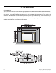
INSTALLATION LOCATING YOUR GAS FIREPLACE 1) When selecting a location for your stove, ensure that the clearances outlined on this page are met. 2) P r o v i d e a d e q u a t e c l e a r a n c e s f o r servicing. 3) The appliance must be installed on a flat, solid, continuous surface (e.g. wood, metal, concrete). This may be the floor, or raised up on a platform to enhance its visual impact.
Regency® P36-4 Gas Log Fireplace Diagram 2 Note: A non-combustible mantel may be installed at a lower height if the framing is made of metal studs covered with a non-combustible board. Note: Ensure the paint that is used on the mantel and the facing is "heat resistant" or the paint may discolour. These drawings are to scale at 1:6 (one inch = 6 inches) Mantel can be installed anywhere in shaded area or higher using the above scale.
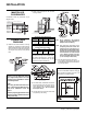
INSTALLATION MANTEL LEG CLEARANCES 2) Frame in the enclosure for the unit with framing material. Combustible mantel leg clearances as per diagram below: 38m m Maximum 38mm projection 51m m at 51mm minimum 127m m clearance. Allow able m antelleg 76m m M antelleg 152m m Side W all M antelleg P36 Fireplace projection. FRAMING AND FINISHING 1) Determine the total thickness of facing material (e.g. drywall plus ceramic tiles) to allow the finished surface to be flush with the front of the unit.
INSTALLATION UNIT ASSEMBLY PRIOR TO INSTALLATION 1) Mount Top Facing Support using the 3 supplied screws into the three pre-punched screw holes on the top front of the unit. Use hole positions A, B, or C depending on your facing depth. The Top Facing Support, the Side Nailing Strips and the 2 Top Standoffs must be correctly positioned and attached to the top before unit is slipped into position.
INSTALLATION EXTERIOR FLUE TERMINATION LOCATIONS Minimum clearances required for balanced flue terminals or the flue terminals of outdoor appliances according to AS5601-2004 (AGA gas installation code) or NZS 5261 (New Zealand) Minimum Clearance (mm) a b c d e f g h j k Below eaves, balconies or other projections: - Appliances up to 50 MJ/h input 300 - Appliances over 50 MJ/h input 500 From the ground or above a balcony 300 From a return wall or external corner 500 From a gas meter (M) 1000 From an electr
INSTALLATION FLUEING Regency® Direct Vent System (Flex) Horizontal Terminations Only These flueing systems, in combination with the P36 Room Sealed Gas Fireplace, have been tested and listed as a Direct Vent type flue system by the Australian Gas Association. The location of the termination cap must conform to the requirements in the Flue Terminal Locations diagram in section "Exterior Flue Termination Locations.
INSTALLATION SIMPSON DURA-VENT FLUEING Horizontal or Vertical Terminations The Simpson Dura-Vent Co Axial Flue System offers a complete line of component parts for installation of both horizontal and vertical installations. Many items are offered in decorative black, as well as galvanized finish. We recommend using the galvanized finish for installation with the P36.
INSTALLATION FLUEING ARRANGEMENTS - HORIZONTAL TERMINATIONS SIMPSON DURA-VENT DIRECT VENT GS SYSTEM and REGENCY® DIRECT VENT SYSTEM (FLEX) (LPG & NG) The diagram shows all allowable combinations of vertical runs with horizontal terminations, using one 90o elbow (two 45o elbows equal one 90o elbow). Note: Must use optional flue adapter (Part # 510-994) when using Simpson Dura-Vent pipe.
INSTALLATION FLUEING ARRANGEMENTS - HORIZONTAL TERMINATIONS SIMPSON DURA-VENT DIRECT FLUE GS SYSTEM and REGENCY® CO AXIAL FLUE SYSTEM (FLEX) (LPG & NG) The diagram below shows examples of horizontal termination arrangements using two 90o elbows (two 45o elbows equal one 90o elbow). Note: 1) 2) 3) 4) A maximum of two 90o elbows are permitted. A minimum of 6 ft. (1.8m) vertical from base of unit is required if two 90o elbows are used. Minimum distance between elbows is 2 ft. (0.6m).
INSTALLATION FLUEING ARRANGEMENTS - VERTICAL TERMINATIONS SIMPSON DURA-VENT CO AXIAL FLUE GS SYSTEM (LPG & NG) The P36 is approved for a 23 ft. (7.0m) vertical, with a maximum 12 ft. (3.7m) horizontal offset using two 90o elbows (two 45o elbows equal one 90o elbow) with Simpson Dura-Vent Co Axial Flue GS flue systems for LPG and NG, as per diagram 1. The P36 is approved for a 37 ft. (11.3m) straight vertical, including a 20" (0.
INSTALLATION The P36 is approved for a 37 ft. (11.3m) straight vertical, with Simpson Dura-Vent Co Axial Flue GS flue systems for LPG and NG, as per the diagram 3. The shaded area in the diagram 3 shows all allowable combinations of straight vertical and offset to vertical terminations with Simpson DuraVent Co Axial Flue GS flue systems for LPG and NG. Maximum two 45o elbows allowed. • • • Flue must be supported at offsets Firestops are required at each floor level and whenever passing through a wall.
INSTALLATION HORIZONTAL TERMINATIONS Install the flue system according to the manufacturer's instructions included with the components. 1) Set the unit in its desired location. Check to determine if wall studs or roof rafters are in the way when the flueing system is attached. If this is the case, you may want to adjust the location of the unit. Rough in the gas preferably on the right side of the unit and the electrical (junction block is on the left side) on the left.
INSTALLATION VERTICAL TERMINATIONS 1) M a i n t a i n t h e 1 - 1 / 4 " clearances (air spaces) to combustibles when passing through ceilings, walls, roofs, enclosures, attic rafter, or other nearby combustible surfaces. Do not pack air spaces with insulation. Check section "Simpson Duravent Flueing" for the maximum vertical rise of the flueing system and the maximum horizontal offset limitations. Diagram 1 2) Set the gas appliance in its desired location.
INSTALLATION Conversion Kit #513-968 from NG to LPG THIS CONVERSION MUST BE DONE BY A QUALIFIED GAS FITTER IF IN DOUBT DO NOT DO THIS CONVERSION !! Conversion Kit Contains: Qty. Part # Description 1 910-037 LPG Injector (Pilot Orifice) 1 904-390 Burner Orifice #52 1 918-590 Decal "Converted to LPG" 1 908-528 Red "LPG" label 1 904-529 5/32" Allen Key 1 918-546 Instruction Sheet 8) Remove burner orifice with a 1/2" wrench. Use another wrench to hold on to the elbow behind the orifice. Discard orifice.
INSTALLATION P36-NG System Data For 0 to 4500 feet altitude Burner Inlet Orifice Sizes: #37( 2.65mm) Max. Input Rating Min. Input Rating 33 mj 20 mj Supply Pressure min.1.25 kPa Manifold Pressure (High) 0.9 kPa Electrical: 240 V A.C. System. Circulation Fan: variable speed 130 CFM. Log Set: Ceramic fibre, 7 per set.
INSTALLATION 4) Light the pilot and turn the valve to "ON" position. 5) The pressure check should be carried out with the unit burning and the setting should be within the limits specified on the safety label. OPTIONAL BRICK PANELS LOG SET INSTALLATION 1) Undo the bottom 2 door latches and open and remove glass door. Remove logs. Read the instructions below carefully and refer to the diagrams. If logs are broken do not use the unit until they are replaced.
INSTALLATION 02-49 02-49 02-53 8) Position Log 02-54 across the cutouts in Logs 02-51 and 02-53. The notch in the bottom right end fitting against the 5th grate tab. 02-51 02-54 6) Place the bottom left front edge of Log 02-55 against the rear bracket on the burner tray and rest the log on the cutout on Log 02-53. 02 -5 3 02-51 02-49 5th Grate Tab 02-55 4) Place Log 02-51 on the front right side of the burner.
INSTALLATION 10) Place the embers on the front of the burner tray in the places shown on the photo. 02-49 02-55 02-52 02-50 Place embers in these 3 locations on the burner tray. 3 -5 02 02-51 02-54 11) Test fire to ensure proper light off (make sure flame flows smoothly from one end of burner to the other). If there is any flame hesitation, check that area for any blockage of the burner ports. Embers STANDARD FLUSH DOOR The standard flush door comes with a black frame.
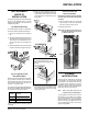
INSTALLATION PREMIUM FLUSH FRONT INSTALLATION 1) Unplug the power source. 6) Remove the manual control switch bracket by undoing the 2 screws. 2) Remove the top louver (if fitted) by carefully pulling it out. 3) Install the premium flush front top louver in place by sliding the louver tabs into the louver brackets on the inside top of the firebox. Louver Tab 7) Remove the burner ON/OFF switch from the bracket using a pair of pliers and remove the 2 screws that secure the 2 wires on the valve.
INSTALLATION 9) Connect the female connecter on the white wire to the TH terminal of the valve. 12) Place the wire grommet back into the thermodisc cover with the 2 female ends of the wires inside the cover as shown. 10) Remove the thermodisc cover from the thermodisc plate by undoing the 2 screws and then remove the wire grommet. 13) Connect the female ends of the red and white wires to the thermodisc.
INSTALLATION 15) Connect the thermodisc wire harness to the new valve/module wire harness. Refer to the wiring diagram on next page for details. 22) Install the wire cover by fitting the 3 clips onto the flange at the front of the firebox. See note below for P36 units. 16) Mount the thermodisc bracket to the adjustable bracket using 2 screws. Important: Thermodisc location is crucial, check the data badge to identify unit and secure to screw location accordingly.
INSTALLATION Option 1: WALL SWITCH Option 2: REMOTE CONTROL Option 3: WALL THERMOSTAT 1) Run supplied 15' of wire through the right or left side gas inlet opening. Be careful not to damage wire. Use the Regency® Remote Control Kit approved for this unit. Use of other systems may void your warranty. A wall thermostat may be installed if desired, connect the wires as per the wiring diagram. Use chart below to determine the maximum wire length.
INSTALLATION WIRING This heater does not require a 240V A.C. supply for the gas control to operate. A 240V A.C. power supply is needed for the fan/blower operation. Caution: Ensure that the wires do not touch any hot surfaces and are away from sharp edges. CAUTION: Label all wires prior to disconnection when servicing controls. Wiring errors can cause improper and dangerous operation.
INSTALLATION WIRING WITH PREMIUM FLUSH FRONT OPTION Regency® P36-4 Gas Log Fireplace 29
OPERATING INSTRUCTIONS OPTIONAL FAN 7) Slide the thermodisc into the bracket clip on the underside of the firebox. 8) Connect black wire from fan to the thermodisc. 240 Volt AC power is needed for the fan switch and blower. The fan can be hard wired if desired. A terminal block is provided on the left hand side of the unit. A three wire power cord can also be used and plugged into a suitable receptacle. 1) Read and understand these instructions before operating this appliance.
OPERATING INSTRUCTIONS LIGHTING PROCEDURE 1) Push in gas control knob slightly and turn to “PILOT” position. 2) Push in control knob all the way and hold in until the pilot lights up. Continue to hold the control knob in for about 20 seconds after the pilot is lit. Release knob. 3) Push in gas control knob slightly and turn to "ON" position. 4) Turn ON the flame switch. FIRST FIRE The first fire in your stove is part of the paint curing process.
OPERATING INSTRUCTIONS COPY OF THE LIGHTING PLATE INSTRUCTIONS MAINTENANCE INSTRUCTIONS FOR YOUR SAFETY READ BEFORE LIGHTING 1) Always turn off the gas valve before cleaning. For relighting, refer to lighting instructions. Keep the burner and control compartment clean by brushing and vacuuming at least once a year. When cleaning the logs, use a soft clean paint brush as the logs are fragile and easily damaged.
MAINTENANCE 3) Check for evidences of excessive condensation, such as water droplets forming in the inner liner, and subsequently dripping out the joints, Continuous condensation can cause corrosion of caps, pipe, and fittings. It may be caused by having excessive lateral runs, too many elbows, and exterior portions of the system being exposed to cold weather. 4) Inspect joints, to verify that no pipe sections or fittings have been disturbed, and consequently loosened.
MAINTENANCE 10) Undo the pilot tube from the valve with a 7/16" spanner. INSTALLING VALVE 11) Undo the quick drop out thermocouple nut on the valve with a 9mm (metric) spanner. 1) Attach the valve to the valve bracket with the 4 (m5x8 metric) screws provided. 12) Remove the Piezo igniter wire and push button assembly. 2) Reconnect the "gas out" flare fitting with an 11/16" spanner. 4) Remove the logs. 13) Undo the "gas out" flare nut with a 13/16" spanner.
PARTS LIST MAIN ASSEMBLY Part # Description 1) 2) 3) 4) 6) 7) 8) 9) 10) 12) 910-142 * 948-045 948-025 510-125 910-006 510-126 910-140 910-246 910-169/P 910-520 910-714 Thermodisc-Fan Auto ON/OFF Thermodisc Bracket Chain Spring Terminal Block Housing Terminal Block Terminal Block Cover Fan Switch HIGH/OFF/LOW Burner Switch ON/OFF Fan Motor Wire Harness Power Cord (240 V) 14) 15) 17) 20) 21) 22) 23) 24) 27) 28) 30) 31) 510-026 948-253 * 510-033 510-064 510-153 510-011 511-044 * * * * Hinge Bracket - Le
PARTS LIST BURNER ASSEMBLY & LOG SET Part # Description 513-560/P 513-562/P 52) * 53) 430-055 54) 910-421 55) 910-422 57) 910-478 58) * 59) * 65) * 66) 910-038 910-039 904-240 904-390 910-036 910-037 936-170 67) * 68) W840470 Valve Assy - NG Valve Assy - LPG Valve Tray -NG Gasket - Valve Access Plate Pilot ON/OFF 3" Extension Knob HI/LOW 3" Extension Knob S.I.T. Valve - NG/LPG Valve Bracket Firebox Base Pilot Bracket Pilot Assy-NG 3 way flame-S.I.T. Pilot Assy-LPG 3 way flame-S.I.T.
PARTS LIST BAY FRONT ASSEMBLY 103) 107) 108) 111) Part # Description 780-931 Bay Front Complete 940-092/P Side Glass 936-243 Glass Gasket - Soft Fibre Black 940-094/P Center Glass 780-905 Brick Panel Inlay - Rustic Brown Bay 780-906 Brick Panel Inlay - Old Town Red Bay 780-938 780-936 112) * Bay Front Trim - Brass Bay Front Trim - Steel Bay Front Trim -Top/Bottom 780-934 113) * 114) * Bay Door Trim - Gold Bay Door Trim-Gold-Bottom Bay Door Trim-Gold-Top Part # Description 510-988 510-990 510-992 51
PARTS LIST FLUSH FRONT ACCESSORIES Part # Description 132) 512-518 135) 940-090/P 136) 936-155 904-691 Flush Door Assembly Glass (Flush) Glass Gasket (Tadpole) U-Clip (each) 510-920 510-921 510-922 510-923 138) * 139) * Flush Louvres - Gold/Black Flush Louvres - Brass/Black Flush Louvres - Black Flush Louvres - Steel/Black Flush Louvre Assy-Top Flush Louvre Assy-Btm 510-954 146) * 148) * Barcelona Surround - Black Barcelona Assy Barcelona Louvre Assy 510-932 150) * Flush Glass Trim - Gold (2/Set) F
PARTS LIST PREMIUM FLUSH FRONT ASSEMBLY 180) 181) 182) 183) Part # Description 516-916 513-948 910-975 * * * * Premium Flush Front - Black Wiring Thermodisc Top Louver Bottom Louver Thermodisc Mounting Bracket Spacers *Not available as a replacement part.
PARTS LIST CAST FACEPLATE ASSEMBLY Part # Description 513-971 201) * 202) * 203) * Cast Faceplates (Set) - Black Metallic Cast Faceplate - Right Cast Faceplate - Top Cast Faceplate - Left 513-991 204) * 205) * Cast Grills (Set) - Black Metallic (Aust. only 240 volt) Cast Grill - Top Cast Grill - Bottom 513-976 201) * 202) * 203) * Cast Faceplates (Set) - Black Enamel Cast Faceplate - Right Cast Faceplate - Top Cast Faceplate - Left 513-996 204) * 205) * Cast Grills (Set) - Black Enamel (Aust.
NOTES ___________________________________________________ ___________________________________________________ ___________________________________________________ ___________________________________________________ ___________________________________________________ ___________________________________________________ ___________________________________________________ ___________________________________________________ ___________________________________________________ ______________________________________
NOTES ___________________________________________________ ___________________________________________________ ___________________________________________________ ___________________________________________________ ___________________________________________________ ___________________________________________________ ___________________________________________________ ___________________________________________________ ___________________________________________________ ______________________________________
WARRANTY Regency® Fireplace Products are designed with reliability and simplicity in mind. In addition, our internal Quality Assurance Team carefully inspects each unit thoroughly before it leaves our door. FPI is pleased to extend this limited lifetime warranty to the original purchaser of a Regency® Product.
© Copyright 2007, FPI Fireplace Products International Ltd. All rights reserved.